

Liquid metering system
a liquid metering and flow rate technology, applied in the field of properties measurement, can solve the problems of limiting the accuracy of delivery of pharmaceuticals to +/20%, not achieving an improvement in the accuracy of delivery of pharmaceuticals, and further compounding the problem
- Summary
- Abstract
- Description
- Claims
- Application Information
AI Technical Summary
Benefits of technology
Problems solved by technology
Method used
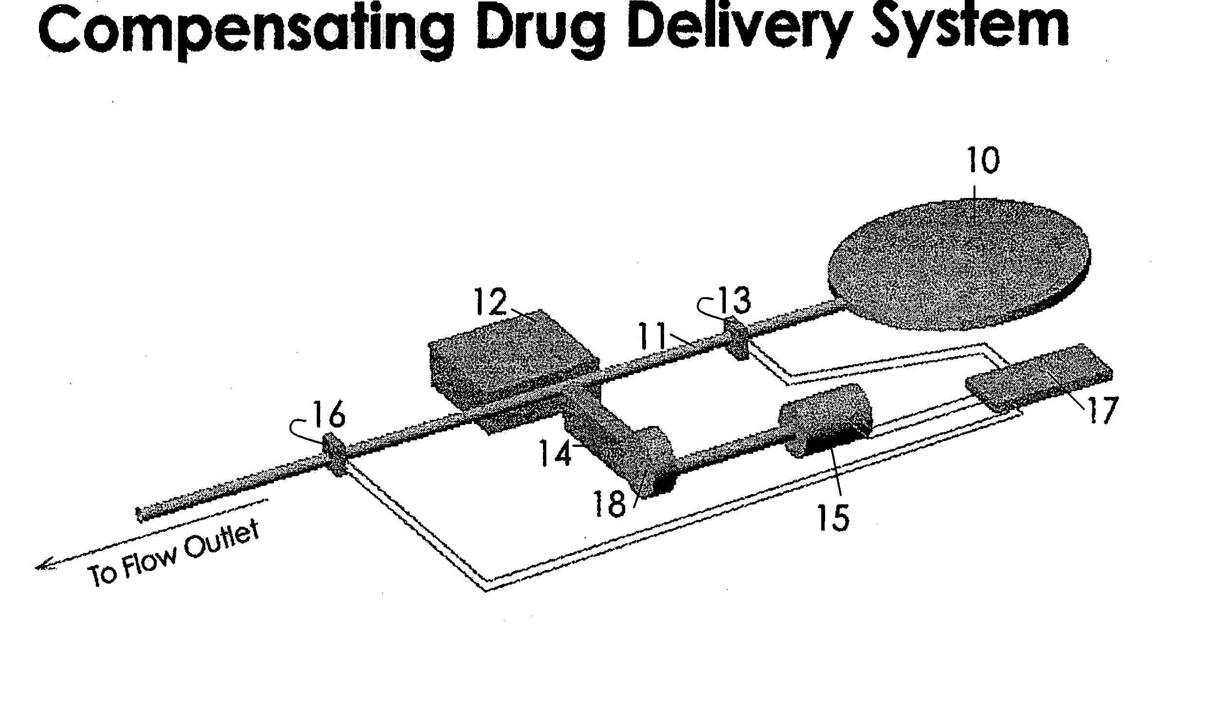
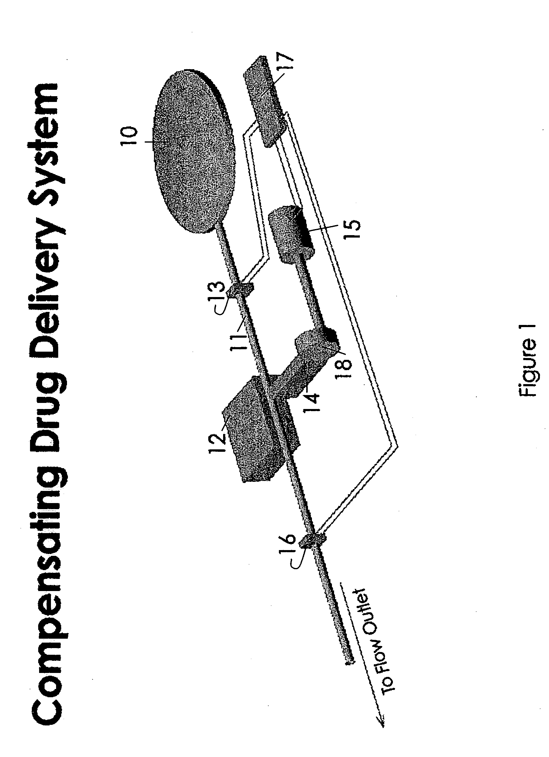
Image

Examples
first embodiment
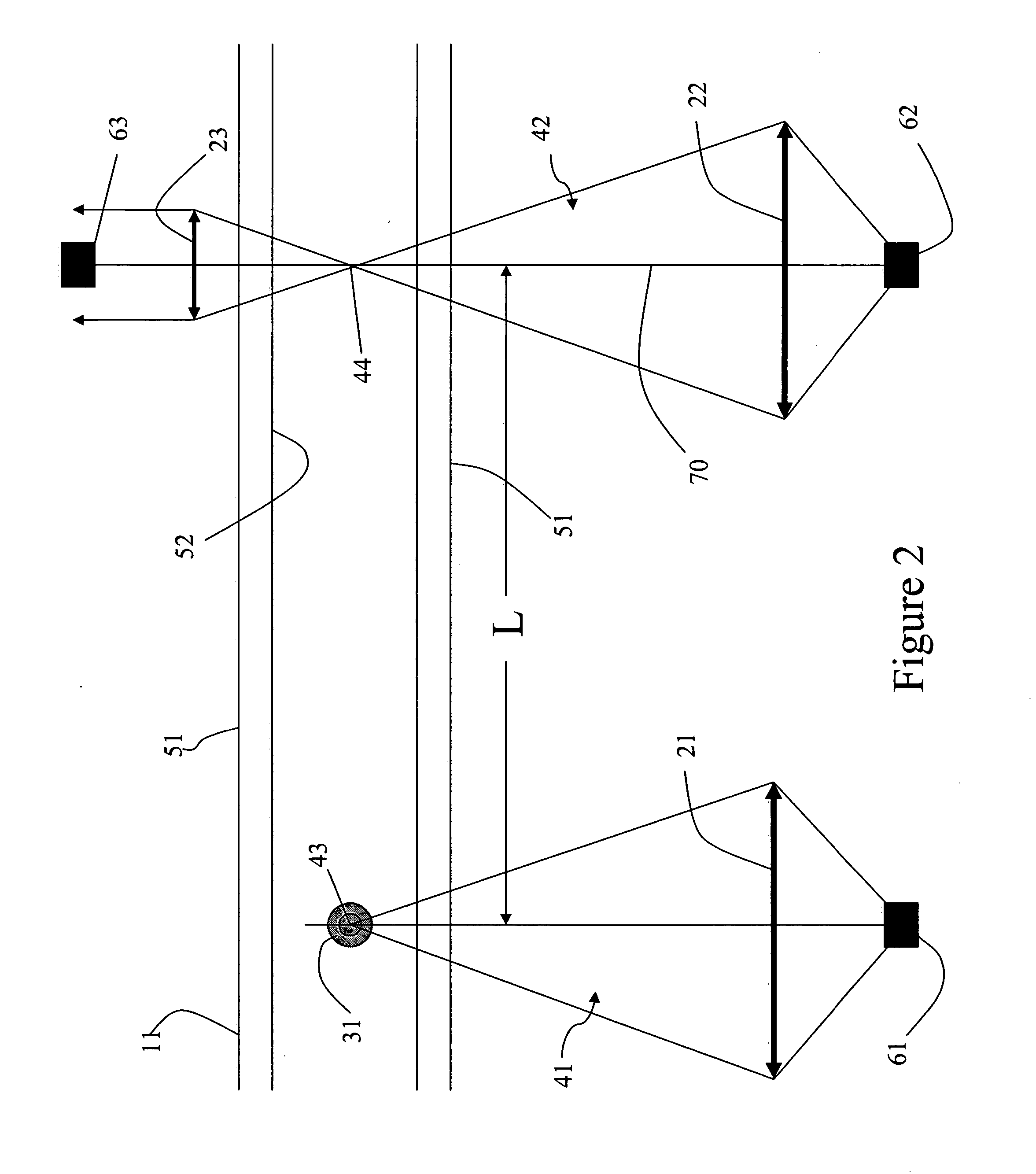
[0039] In FIGS. 2 through 4, the separation distance of locations 43 and 44 is either predetermined, known or measured. In a first embodiment, the fluid is not flowing when an increment of fluid is heated by heat source 61. Shortly after heating the increment of fluid, flow is started. The time required for the heated increment of fluid to flow from location 43 where it was heated to location 44 where it is detected is measured as the elapsed time from the time of starting fluid flow to the time of detection of the heated increment at location 44. This time interval is termed the thermal time of flight. The velocity of the fluid may be calculated by dividing the thermal time of flight into the separation distance.
second embodiment
[0040] In FIGS. 2 through 4, the fluid is flowing at the time an increment of fluid is heated at location 43. At a desired time after initiation of flow, an increment of fluid is heated, and the elapsed time from time of heating to time of detection at location 44 is measured to determine the thermal time of flight. The velocity of the fluid may be calculated by dividing the thermal time of flight into the separation distance.
[0041] Further embodiments may be envisioned to take advantage of the invention. In one such embodiment, a second optical source and detector pair for detecting the heated increment of liquid is located at a third location downstream of location 44 in FIGS. 2 through 4. In such an embodiment, the thermal time of flight may be measured as the elapsed time for the heated increment to move from location 44 to the third location further downstream. And the fluid velocity may be calculated as the thermal time of flight divided into the distance of separation of the ...
PUM
 Abstract
Description
Claims
Application Information