Collet-type splice and dead end use with an aluminum conductor composite core reinforced cable

Inactive Publication Date: 2005-01-13
CTC GLOBAL CORP
View PDF4 Cites 24 Cited by
  • Summary
  • Abstract
  • Description
  • Claims
  • Application Information

AI Technical Summary

Benefits of technology

A collet-type fitting uses a collet inside a collet housing to hold the composite cores. The composite core cables can be stripped of the aluminum conductor to provide the best bond between the collet and the composite core, which is the load-bearing member of the cable. After inserting the composite core into the collet, a compression implement may be used to compress the collet against the composite core. The shape of the collet housin

Problems solved by technology

Unfortunately, methods and systems to install these cables have yet to be created.
These c

Method used


Image

  • Collet-type splice and dead end use with an aluminum conductor composite core reinforced cable
  • Collet-type splice and dead end use with an aluminum conductor composite core reinforced cable
  • Collet-type splice and dead end use with an aluminum conductor composite core reinforced cable

Examples


Embodiment Construction

The present invention will now be described more fully hereinafter with reference to the accompanying drawings, in which exemplary embodiments of the invention are shown. This invention may, however, be embodied in many different forms and should not be construed as limited to the embodiments set forth herein. Rather, these embodiments are provided so that the disclosure will fully convey the scope of the invention to those skilled in the art. The drawings are not necessarily drawn to scale but are configured to clearly illustrate the invention. The invention is as set forth in the claims. Throughout this description, the term “couple”, “couples”, or “coupled” means any type of physical attachment or connection of two parts.

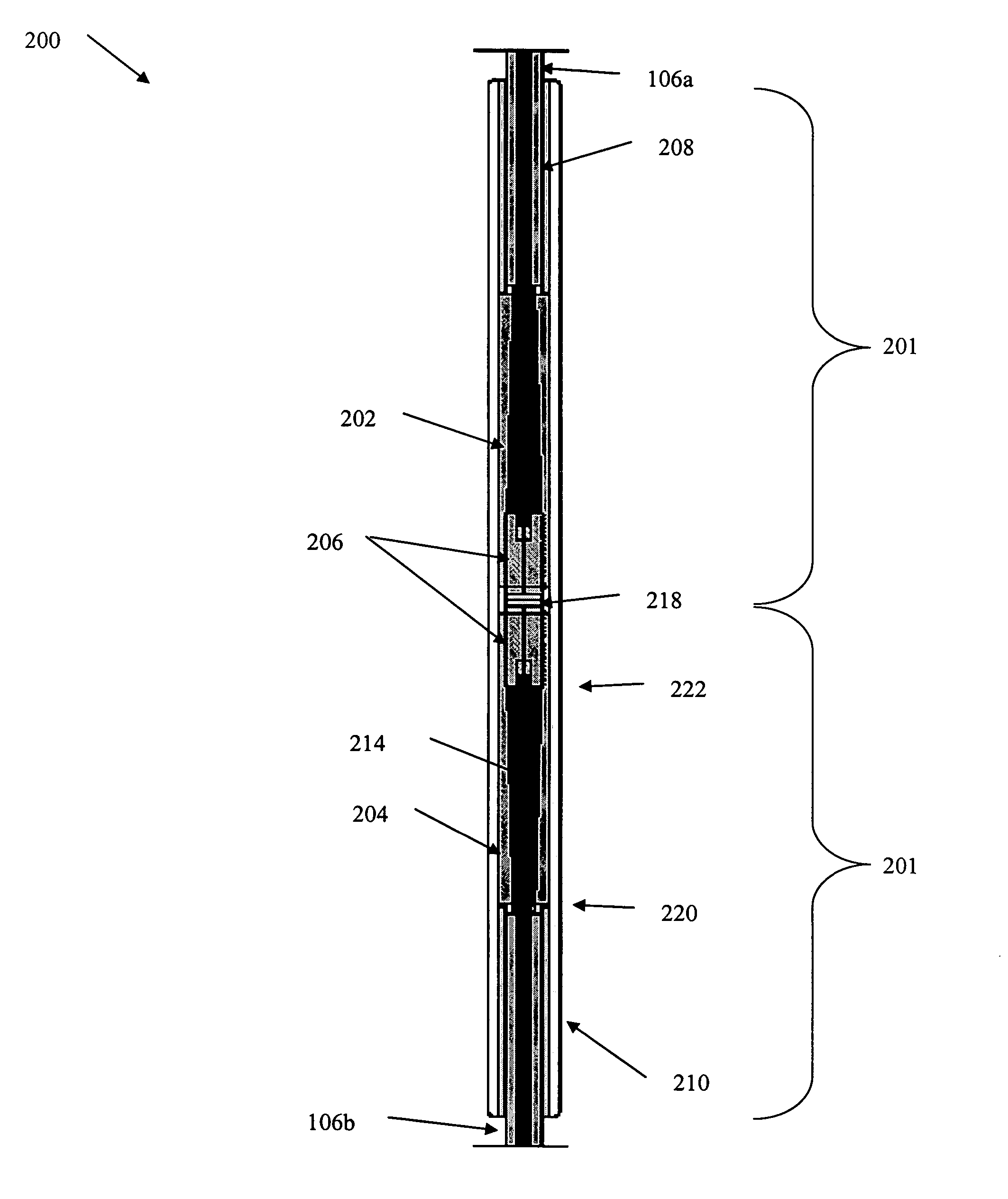
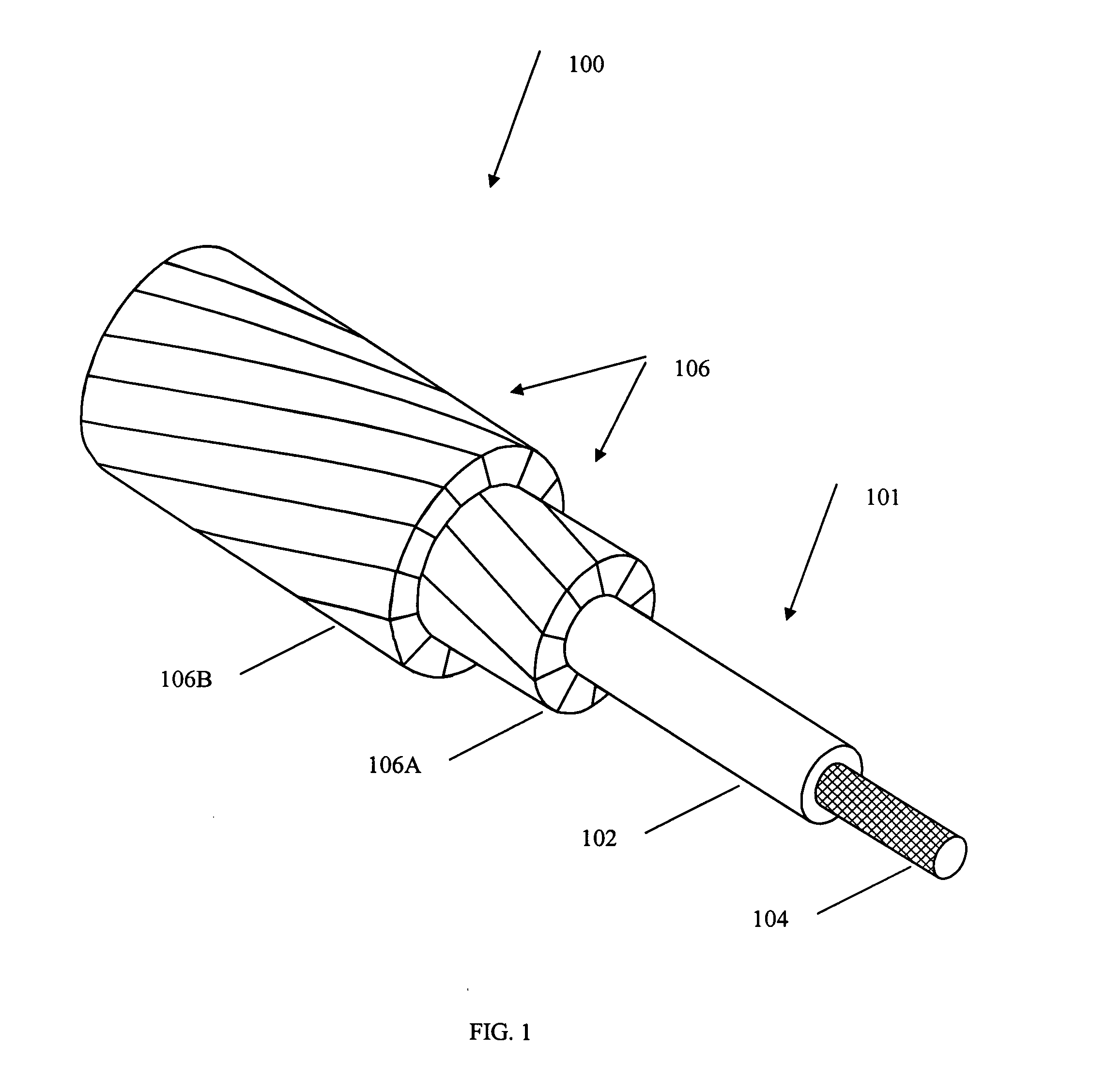
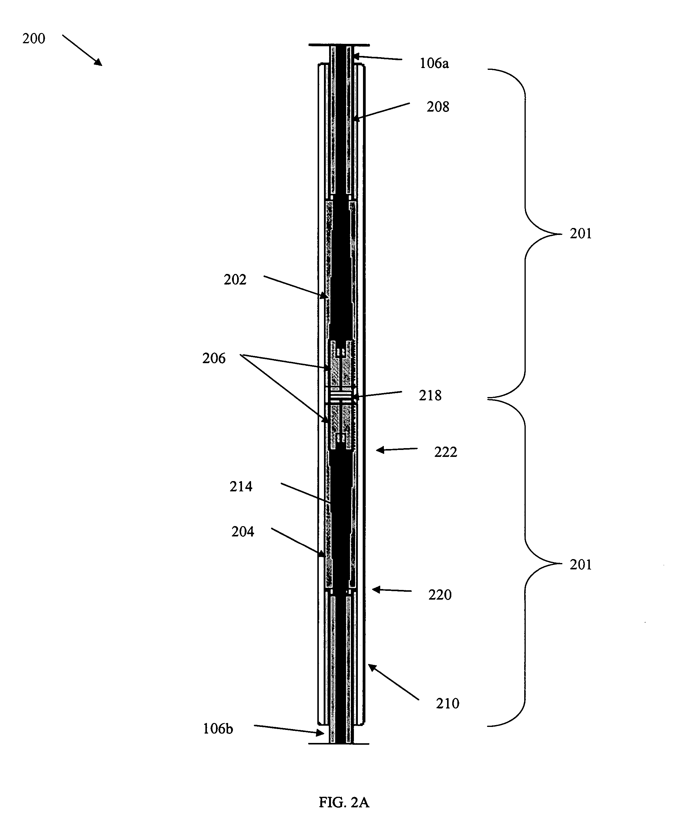
The present invention relates to methods and apparatuses to splice together two composite core 101 reinforced cables. FIG. 1 illustrates one embodiment of an ACCC reinforced cable 100. FIG. 1 illustrates an ACCC reinforced cable 100 having a reinforced carbon ...


PUM

PropertyMeasurementUnit
Luminous fluxaaaaaaaaaa
Pressureaaaaaaaaaa
Pressureaaaaaaaaaa

Abstract

This invention relates to collet-type splices and collet-type dead ends and methods for splicing together two aluminum conductor composite core reinforced cables (ACCC) or terminating one ACCC cable. The collet-type fittings use a collet inside a collet housing to hold the composite cores. The composite cores can be stripped of the aluminum conductor to provide a bond between the collet and the composite core. After inserting the composite core into the collet, a compression implement compresses the collet. The collet holds the composite core with frictional forces and the collet further compresses and strengthens the hold on the composite core if the composite core pulls the collet further into the collet housing.

Description

STATEMENT REGARDING FEDERALLY SPONSORED RESEARCH OR DEVELOPMENT Not Applicable REFERENCE TO A “MICROFICHE APPENDIX” Not Applicable BACKGROUND OF THE INVENTION 1. Field of the Invention The present invention relates to apparatuses and methods to splice and terminate electrical cables. More particularly, the invention relates to several fittings capable of joining two composite core cables by the load bearing composite cores and to several fittings that can terminate or dead end the composite core cables. 2. Description of the Related Art The blackouts in 2003 that affected the United States, Great Britain, and France have demonstrated an urgent need to update the world's power grids. An elegant and immediate solution is the replacement of existing conductors with composite core reinforced cables. An example of a composite core reinforced cable, the ACCC cable, is described in PCT Application No. PCT / US03 / 12520, which is incorporated by reference herein. Hereinafter, the ACCC cab...

Claims


Application Information

Patent Timeline
IPC IPC(8): B32B5/02B32B27/04B32B27/12H01RH01R4/50H01R4/62H02G3/06
CPCH01R4/5083H01R4/62H02G7/04H02G15/18H02G15/06H02G15/10H02G7/056H01R4/50
Inventor BRYANT, DAVID
Owner CTC GLOBAL CORP
Why Eureka
Try Eureka