

Pressure induced reagent introduction and electrophoretic separation
a technology of electrophoretic separation and reagent introduction, which is applied in the direction of fluid pressure measurement, liquid/fluent solid measurement, peptide measurement, etc., can solve the problems of parabolic velocity profile of reagents, and achieve the effect of improving fluid control and better separation resolution
- Summary
- Abstract
- Description
- Claims
- Application Information
AI Technical Summary
Benefits of technology
Problems solved by technology
Method used
Image

Examples
example 1
Demonstration of movement on a chip
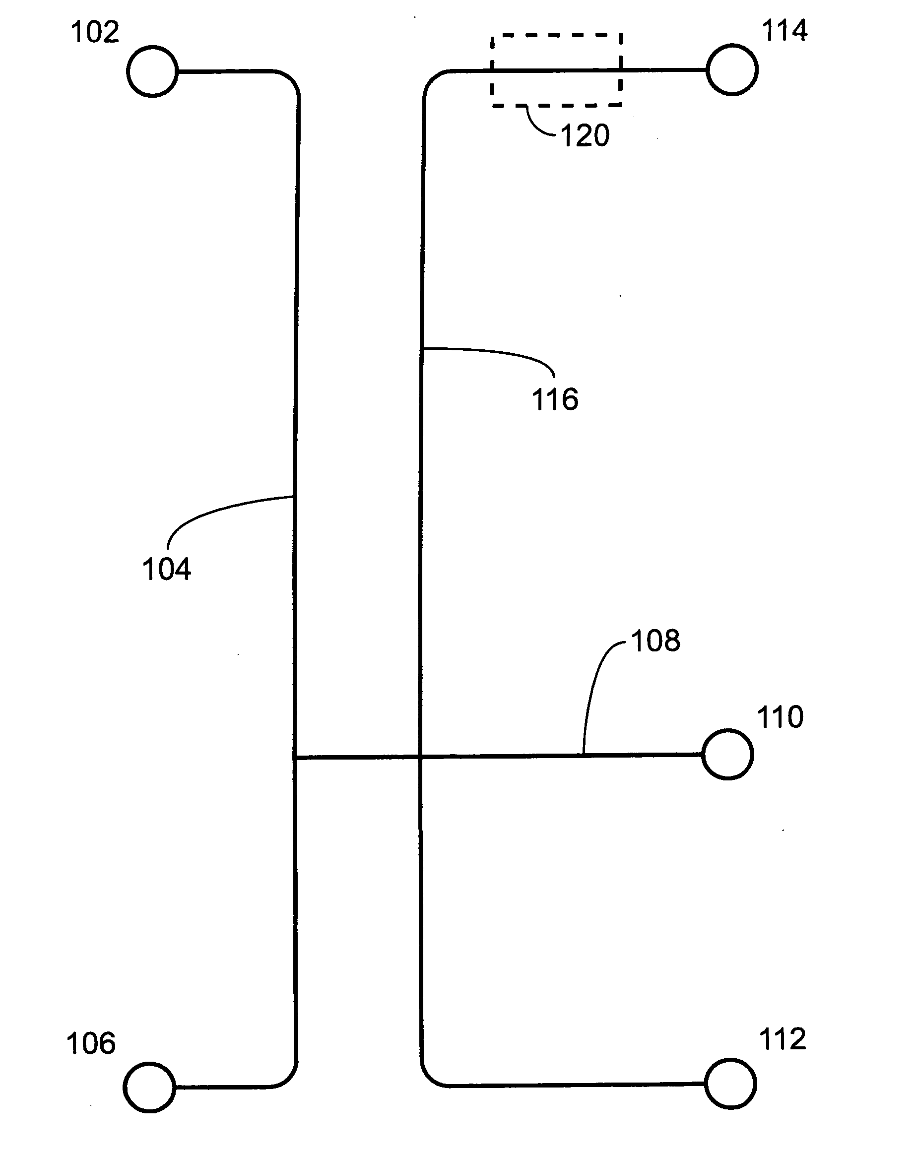
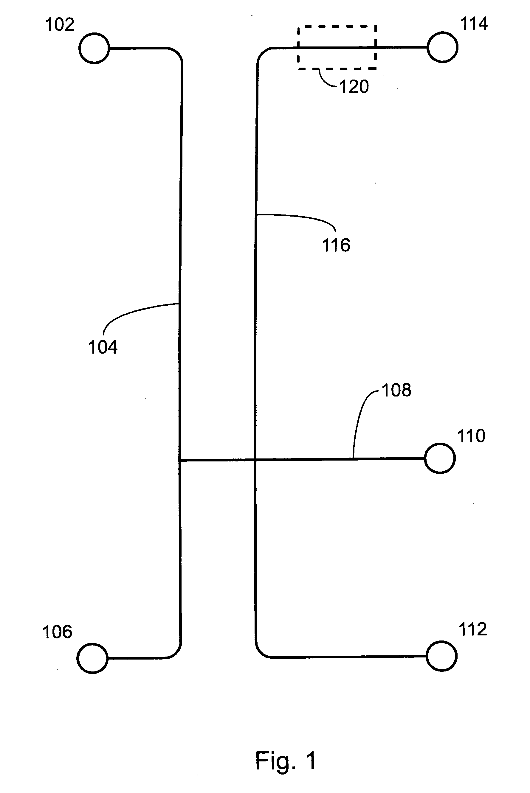
[0140] The microfluidic device of FIG. 1, was used to demonstrate function of the device and perform separations. Reagents were placed in various reservoirs of the device and pumped through using electrokinetic forces and electrokinetic forces combined with pressure. Clean baseline separations were obtained on these devices with all parameter sets.
[0141] An anionic substrate and a neutral marker were used to show that fluid flow, e.g., on a planar device, is completely controlled by electroosmosis and electrophoresis. Fl-Kemptide (40 μM) and Bodipy-Fl-arginine (50 μM) were placed in reservoir 112. A gated injection via reservoir 110 to reservoir 114 showed the channel dimensions in the device were adequate for good separation and the short path length did not hinder detection. Next the probes were loaded into reservoir 102 and electrokinetically moved to reservoir 110. A cross injection using reservoirs 112 and 114 allowed for the volume of fluid...
example 2
PKA Phosphorylation of Fl-Kemptide
[0143] The device shown in FIG. 1 was used to monitor a phosphorylation of Fl-Kemptide by PKA over time. FIG. 6, panel A shows repetitive injections of substrate only overlaid with repetitive injections of PKA and substrate when the reagents were allowed to incubate in reservoir 102. In both instances, the reagents were pumped via pressure driven flow to reservoir 106, loaded electrokinetically to reservoir 110, and then electrokinetically injected into shallow separation channel 116. The evolution of substrate to product is evident from the results shown in FIG. 6, Panel A. The separation is complete even in the presence of pumped flow during the separation step as shown in the magnified view of FIG. 6B. The clear symmetric peak shape indicates that parabolic flow in the shallow separation channel was not significant.
[0144] Experiments were run in a pH 7.5 assay buffer comprising 100 mM HEPES, 1 M NDSB-195, 5 mM MgCl2, 100 μM ATP, 10 mM DTT, and ...
example 3
Performing Separations in a Device Utilizing an Electroosmotic Pump
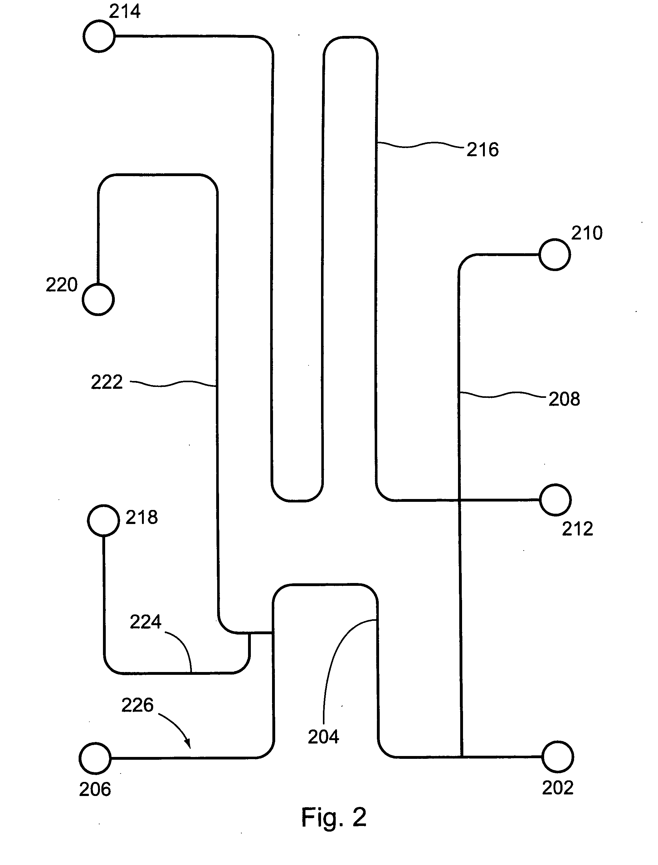
[0146] The microfluidic device in FIG. 2 was used to demonstrate the function and separation efficiency of a device containing an electroosmotic pump. The neutral and cationic rhodamine analogs RhB and Rh6G were separated, as shown in FIG. 7. Experiments were performed in a pH 7.5 assay buffer comprising 100 mM HEPES, 1 M NDSB-195, 5 mM MgCl2, and 0.1% TritonX-100. Reagents were added to the buffers on the day of use.
[0147] First, dyes were placed in reservoir 202 and electrokinetically pumped to reservoir 210. They were then cross-injected and detected about one-third of the length into shallow separation channel 216. Loading of the sample into shallow separation channel 216 and separation of the components were performed with the electroosmotic pump off. The dyes were moved directly by electroosmosis and electrophoresis.
[0148] Second, the electroosmotic pump, comprising shallow pump channel 222, reservoirs 220, ...
PUM
| Property | Measurement | Unit |
|---|---|---|
| Depth | aaaaa | aaaaa |
| Depth | aaaaa | aaaaa |
| Depth | aaaaa | aaaaa |
Abstract
Description
Claims
Application Information