Mechanical support system for devices operating at cryogenic temperature

a technology of mechanical support system and device, which is applied in the direction of machines/engines, vessel construction details, container discharge methods, etc., can solve the problems of material severe thermal contraction at cryogenic temperature, the design of mechanical support system for high temperature superconductor applications faces additional challenges, and the device cryogenic cooling system is a huge burden

Inactive Publication Date: 2005-01-13
SUPERPOWER INC
View PDF5 Cites 6 Cited by
  • Summary
  • Abstract
  • Description
  • Claims
  • Application Information

AI Technical Summary

Benefits of technology

[0005] Briefly, in accordance with one embodiment of the present invention, an apparatus is provided for securing an inner vessel having a bottom and a side wall onto an outer vessel having a bottom wall and a side wall, within a cryogenic system. The inner vessel is at cryogenic temperature while the outer vessel is at a higher temperature such as the room temperature. The outer vessel is sized to envelop the inner vessel, where a vacuum may be maintained in the space between the outer vessel and the inner vessel to provide thermal insulation. Both vessels are nominally concentric with each other relative to the vertical central axis.
[0006] The apparatus comprises at least one bottom-support component and at least one side-support component. The bottom-support component comprises at least one mating structure consisting of at least one pair o

Problems solved by technology

Design of mechanical support systems for cryogenic systems such as those of high temperature superconductor (HTS) applications faces additional challenges compare to similar system for room temperature devices.
One of these challenges is accommodating heat transfers from high temperature parts to lower temperature parts of the device.
Without proper thermal insulation to insulate the cold part of the device from its warm temperature environment, there will be a substantial amount

Method used


Image

  • Mechanical support system for devices operating at cryogenic temperature
  • Mechanical support system for devices operating at cryogenic temperature
  • Mechanical support system for devices operating at cryogenic temperature

Examples


Embodiment Construction

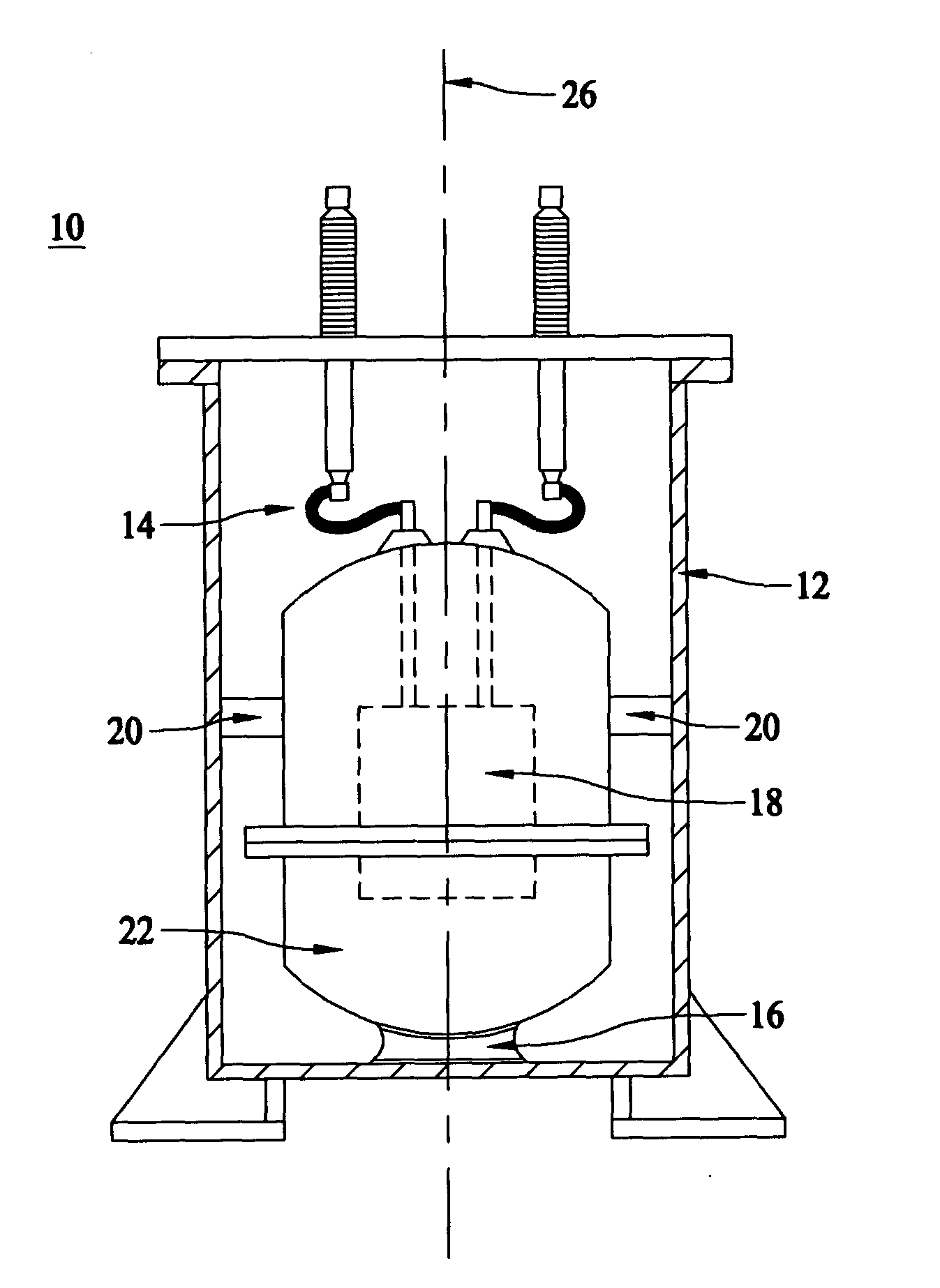
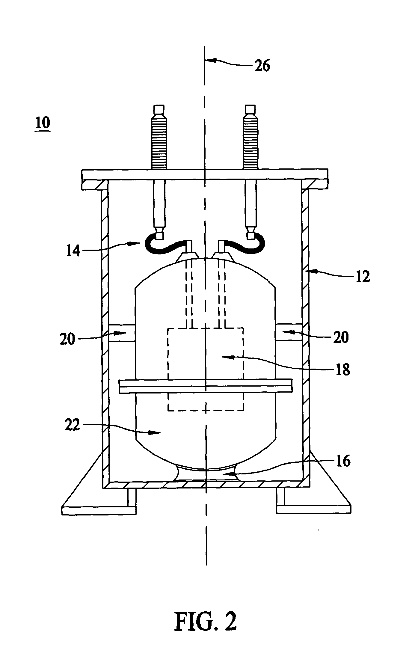
[0016] The present invention is a mechanical support apparatus for a cryogenic device system in which one vessel that houses the device at cryogenic temperature is located within and secured onto another larger outer vessel that is maintained at higher temperature. Such a mechanical support mechanism provides constraints on rotational and planar movements of the inner container vessel, while at the same time achieving minimal physical contact between the inner and outer container vessels and allowing room for thermal contraction during the cool down of the inner vessel. The apparatus comprises at least one bottom-support component and at least one side-support component. Each of these components comprises at least one mating structure of various configurations and is affixed to the surfaces of the inner and outer container vessels by various means.

[0017] The present invention, as illustrated in FIG. 2, provides a mechanical support system 10 for the inner vessel 22 of a cryogenic d...


PUM


Abstract

A mechanical support mechanism for a device operating at cryogenic temperature where the cryogenic container vessel is situated within another larger container vessel. The apparatus provides means to secure the inner vessel to the outer vessel through a bottom-support component and a side-support component. These components consist of mating structures of different configurations that provide inner vessel with constraints for horizontal, lateral, vertical and rotational degrees of freedom while at the same time achieving minimal physical contacts between the inner and outer container vessels to reduce heat leak into the inner cryogenic container.

Description

BACKGROUND [0001] The invention relates generally to a mechanical support system for devices that operate at cryogenic temperature. [0002] Design of mechanical support systems for cryogenic systems such as those of high temperature superconductor (HTS) applications faces additional challenges compare to similar system for room temperature devices. One of these challenges is accommodating heat transfers from high temperature parts to lower temperature parts of the device. Without proper thermal insulation to insulate the cold part of the device from its warm temperature environment, there will be a substantial amount of heat leak into the cryogenic system, thereby generating a tremendous burden on the cryogenic cooling system of the device. Consequently, the mechanical support system for the cryogenic device should be designed to minimize the contacts between the warm part and the cold part of the device in order to minimize the heat leak resulting from these contacts. Another major ...

Claims


Application Information

Patent Timeline
IPC IPC(8): F17CF17C1/00F17C13/08
CPCF17C13/083F17C2270/0527F17C2201/0109F17C2201/032F17C2201/056F17C2203/0391F17C2205/0111F17C2205/0169F17C2221/014F17C2223/0123F17C2223/0161F17C2223/033F17C2223/035F17C2260/033F17C2205/0192
Inventor YUAN, XING
Owner SUPERPOWER INC
Why Eureka
Try Eureka