Step-up/step-down DC-DC converter and portable device employing it

US20050007089A1Active Publication Date: 2005-01-13ROHM CO LTD

Image

  • Step-up/step-down DC-DC converter and portable device employing it
  • Step-up/step-down DC-DC converter and portable device employing it
  • Step-up/step-down DC-DC converter and portable device employing it

Examples


Embodiment Construction

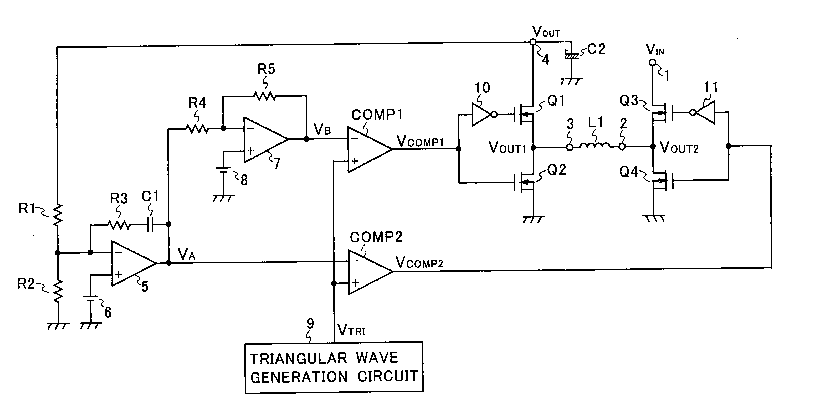
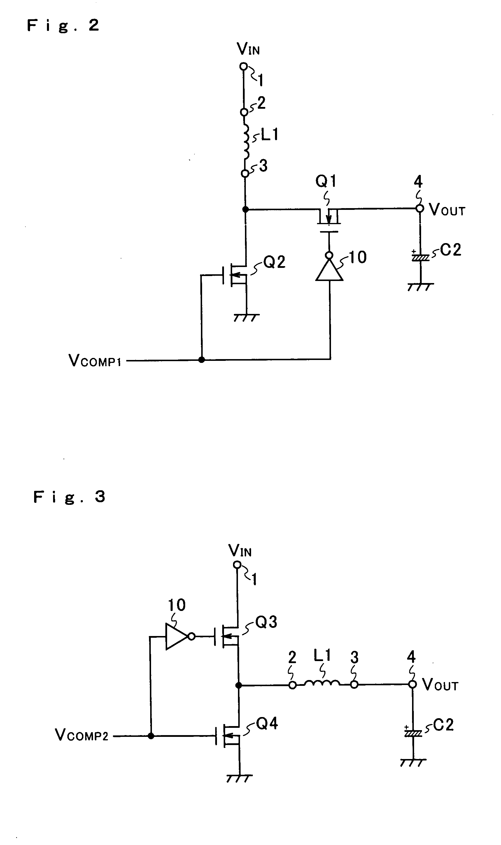
[0029]FIG. 1 shows an example of the configuration of a step-up / step-down DC-DC converter according to the present invention. The step-up / step-down DC-DC converter shown in FIG. 1 receives, as an input voltage VIN thereto, the output voltage of a direct-current power source (not illustrated) such as a battery. The input voltage VIN is applied to an input terminal 1, which is connected to the drain of an n-channel MOS field-effect transistor (hereinafter referred to as an nMOS transistor) Q3. The source of the nMOS transistor Q3 is connected to a terminal 2 and to the drain of an nMOS transistor Q4. The source of the nMOS transistor Q4 is grounded.

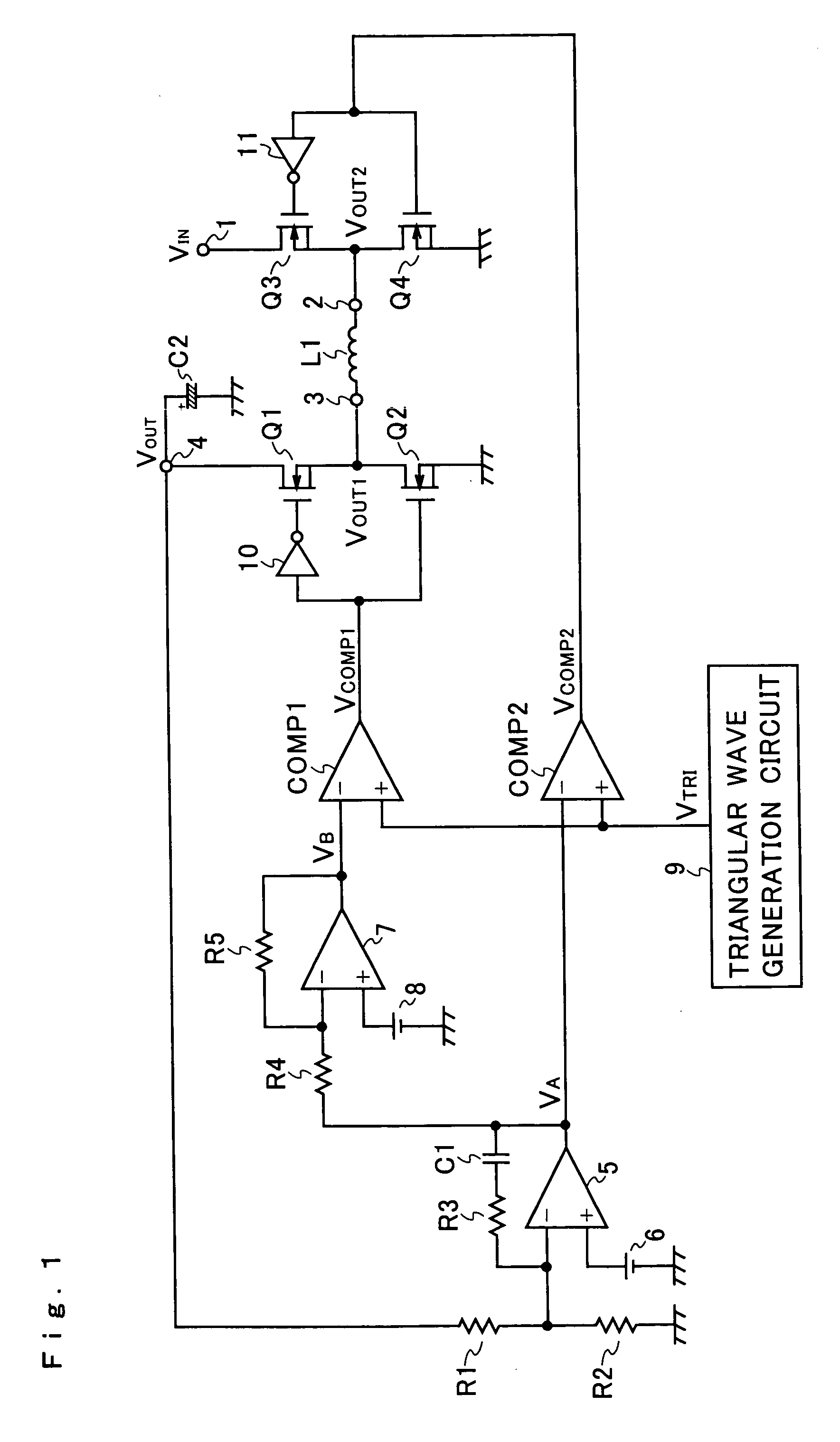
[0030] The terminal 2 is connected through a coil L1 to a terminal 3. The terminal 3 is connected to the source of an nMOS transistor Q1 and to the drain of an nMOS transistor Q2. The drain of the nMOS transistor Q1 is connected to an output terminal 4, and the source of the nMOS transistor Q2 is grounded.

[0031] The output terminal 4 is c...


PUM


Abstract

In a step-up / step-down DC-DC converter, an error signal commensurate with a difference between a voltage commensurate with the output voltage and a predetermined reference voltage and a triangular wave signal are compared by a first comparator, whose output is used to turn on and off a step-up switching circuit. An inverted signal obtained by inverting the error signal and the triangular wave signal are compared by a second comparator, whose output is used to turn on and off a step-down switching circuit. The median level between the outputs of the first and second comparators is set to be lower than the maximum level of the triangular wave signal and higher than the minimum level thereof. Thus, when step-up and step-down modes are switched from one to the other, an overlap period is produced during which the step-up and step-down modes overlap. This makes possible smooth switching between the step-up and step-down modes.

Description

[0001] This application is based on Japanese Patent Application No. 2003-193354 filed on Jul. 8, 2003, the contents of which are hereby incorporated by reference. BACKGROUND OF THE INVENTION [0002] 1. Field of the Invention [0003] The present invention relates to a step-up / step-down DC-DC converter that steps up or down the voltage inputted thereto and outputs the resulting voltage. [0004] 2. Description of the Prior Art [0005] An example of the configuration of a conventional step-up / step-down DC-DC converter is shown in FIG. 6. The conventional step-up / step-down DC-DC converter shown in FIG. 6 is composed of an input voltage monitoring circuit 24 and a step-up / step-down mode switchable DC-DC converter 25. A direct-current source 23 is connected to the input voltage monitoring circuit 24 and to the step-up / step-down mode switchable DC-DC converter 25, so that the output voltage of the direct-current source 23 is used as an input voltage VIN to the conventional step-up / step-down DC-...

Claims


Application Information

Patent Timeline
13 Jan 2005
Publication
US20050007089A1
IPC
H02M3/158; H02M3/155
CPC
H02M3/1582; H02M3/155
Inventors
NIIYAMA, KENICHI; YAMA, MICHIAKI