Rendering successive frames in a graphic object system

Active Publication Date: 2005-01-13
CANON KK
View PDF13 Cites 42 Cited by
  • Summary
  • Abstract
  • Description
  • Claims
  • Application Information

AI Technical Summary

Benefits of technology

The present invention addresses problems with prior rendering systems by taking advantage of temporal coherence between one frame of an animation sequence and the succeeding frame.

Problems solved by technology

This process can be computationally expensive —particularly since sorting of the active edge list cannot be readily implemented as part of a pipelined process.
However, prior art rendering systems described are inefficient in this role, because edges are required to be passed as input on a

Method used


Image

  • Rendering successive frames in a graphic object system
  • Rendering successive frames in a graphic object system
  • Rendering successive frames in a graphic object system

Examples


Embodiment Construction

Table of Contents

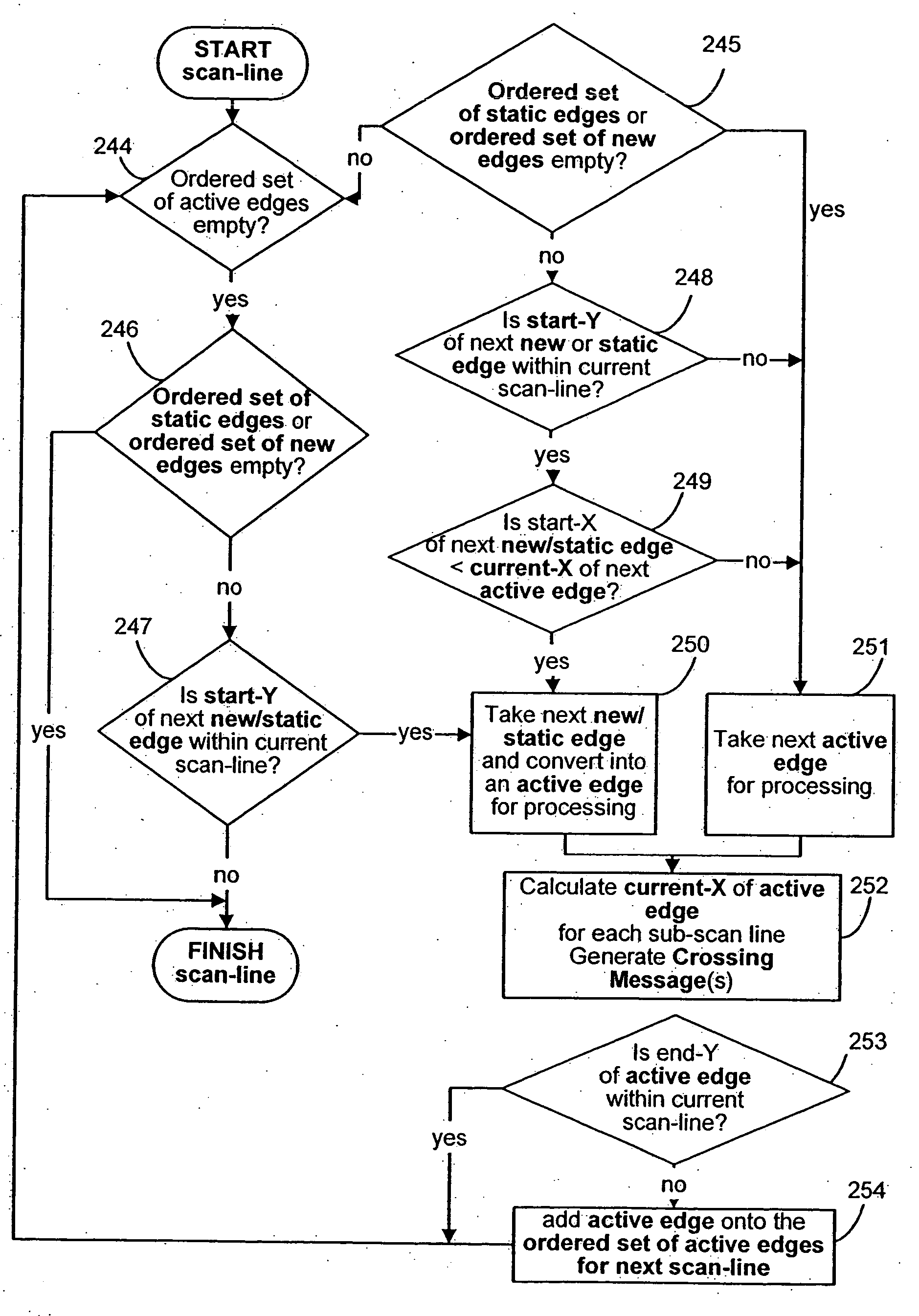
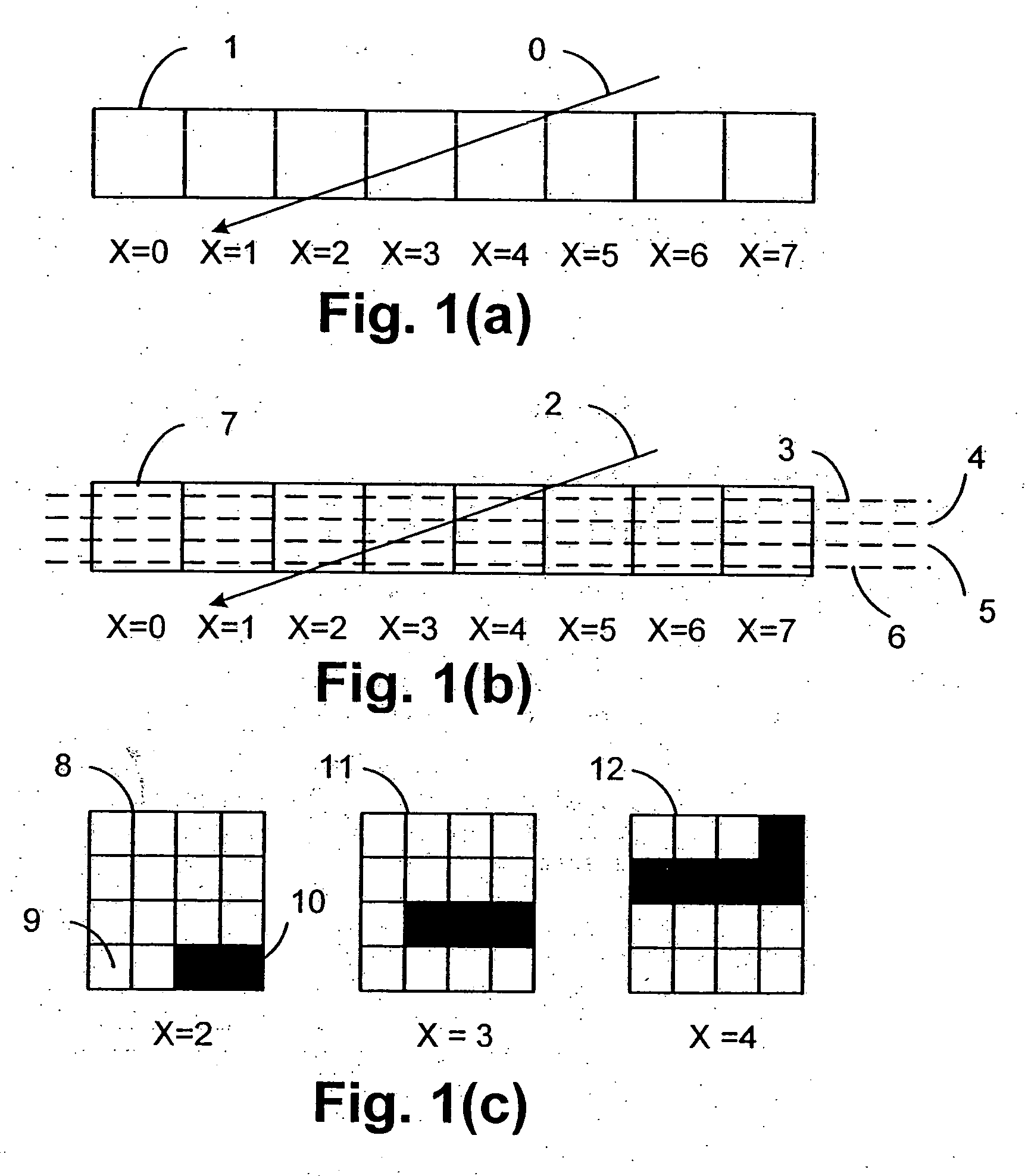
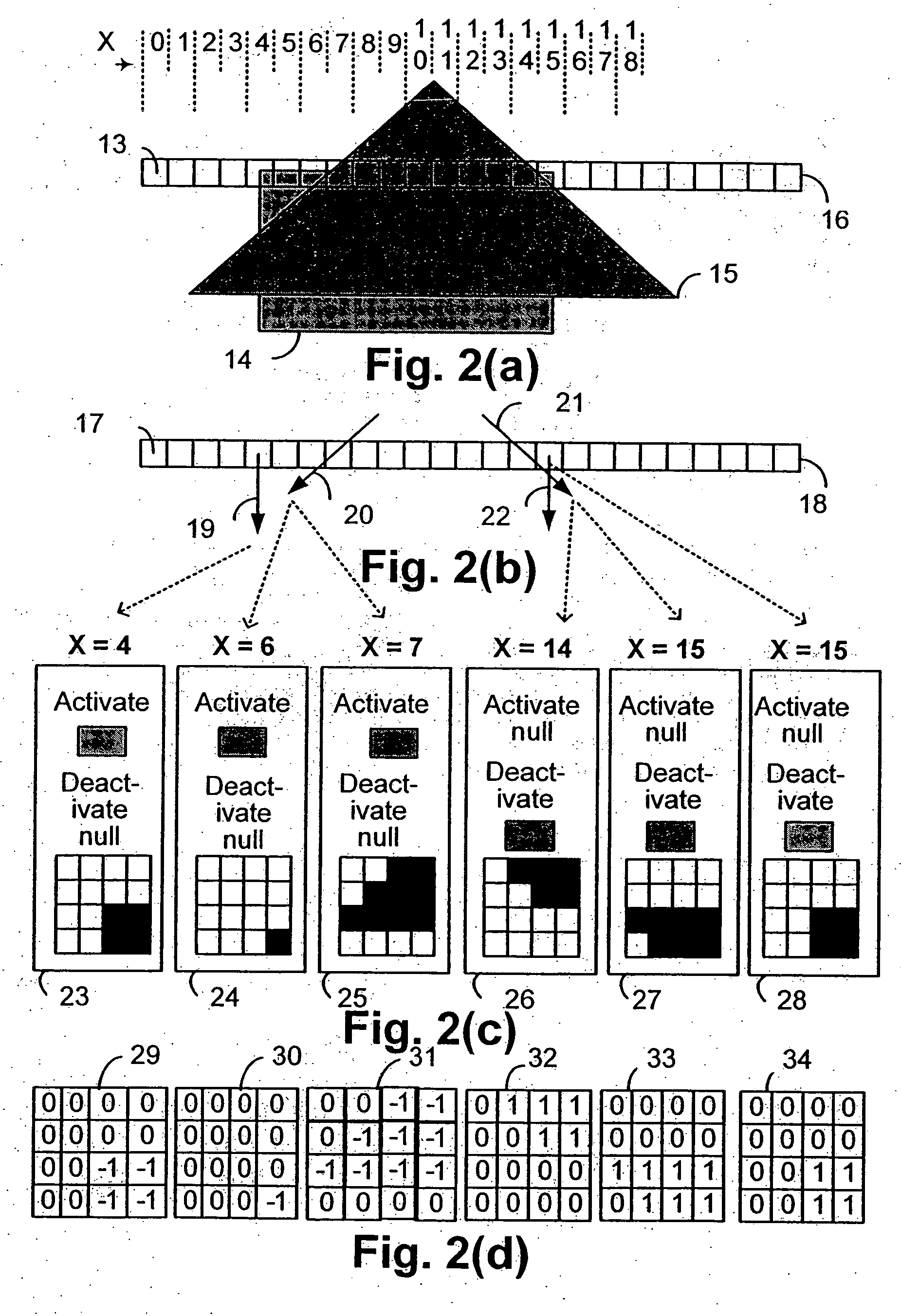
1. Introduction 1.1. Coordinate spaces 1.2. Graphic objects 1.3. Glyphs 1.4. Z-levels 1.5. Stroking 1.6. Morphing 2. The Driver Module 2.1. Sprites 2.1.1. Sprites: transformation matrices 2.1.2. Graphic objects and their depth 2.2. The display list 2.2.1. Frame rendering 2.2.2. Graphic objects and z-levels 2.2.3. Local depths and absolute depths 3. Transformation, Morphing and Stroking 3.1. Morphing 3.2. Transformation 3.3. Generating Edges 3.4. Decomposition of strokes into edges and z-levels 3.4.1. Stroking a straight edge 3.4.2. Stroking a curved edge 3.4.3. Stroking a join 3.4.4. Stroking Equal or Opposite Edge Joins 3.4.5. Generating end-caps at the end of a path 3.4.6. Endcaps between stroked and unstroked edges 3.4.7. Z-level assignments for opaque strokes 3.4.8. Z-level assignments for transparent strokes 3.4.9. Transformation of Stroking Primitives 3.5. Filtering 3.6. Generating edge-tracking parameters 3.6.1. Generating st...


PUM


Abstract

Disclosed is an imaging engine system (699) generally intended for the reproduction of graphical object images using apparatus having limited computing resources, such as so-called “thin clients”. Numerous developments of traditional image processing and rendering enable high quality image generation. One such development takes advantage of temporal coherence between one frame in an animation sequence and the succeeding frame. In particular, there will often be some edges (233, 235) of graphical objects that remain “static” across several contiguous frames. One example of this includes those edges used to draw image background detail. Another development performs antialiasing during scan line rendering of a graphic object image where sub-pixel resolution coverage bit-masks (A-buffers 29-34) are generated for a limited number of scan lines at a time. Preferably the A-buffers are generated for only one pixel at a time. Another development relates to rendering a scan line of a graphic object image in a scan line renderer for a span of pixels lying between two x-order consecutive edges intersecting the scan line. For the span of pixels, this development maintains a subset of depths present in the rendering, the subset being those depths that are present on the span and being maintained in depth order (590) and subject to removal of depths where the corresponding depth is no longer active. In another development a compositing stack (6101-6107) of image layers to be rendered in a raster scan fashion is simplified. Rendering is operable over a run of two or more pixels within which a relationship between graphical objects contributing to the layers does not change. The layers are first divided into groups (6110, 6112, 6114), with each group being separated by a layer having variable transparency (6111, 6113). For a top one of the groups, layers having constant colour in the run are reduced to a single equivalent colour (6115, 6116, 6117) having an associated accumulated contribution. Many other developments are disclosed.

Description

COPYRIGHT NOTICE This patent specification contains material that is subject to copyright protection. The copyright owner has no objection to the reproduction of this patent specification or related materials from associated patent office files for the purposes of review, but otherwise reserves all copyright whatsoever. TECHNICAL FIELD OF THE INVENTION The present invention relates generally to rendering graphical object data and, in particular, to the efficient rendering for the purpose of animating a sequence of frames. BACKGROUND Rendering systems take as input a description of what is required to be displayed on an output device or in a frame buffer. Typically such a description will often include sets of edge or vector data which describe the outline, or parts of, a basic graphical object. For example, a font glyph could be described as such. Additionally, the description may include fill information that informs the rendering system how to select colours for output pixels i...

Claims


Application Information

Patent Timeline
IPC IPC(8): G06T15/70G06T11/00G09G5/36G09G5/38
CPCG06T13/80G06T11/40
Inventor ECOB, STEPHEN EDWARDBRADLEY, SCOTT
Owner CANON KK
Why Eureka
Try Eureka