Image processing method and an image processing apparatus

a processing method and image technology, applied in the field of image processing methods and image processing apparatuses, can solve the problems of insufficient accuracy of computed disparity and inability to provide precise disparity resolution, so as to reduce the necessary processing time and achieve precise disparity (and distance to objects)

Inactive Publication Date: 2015-10-22
MIZUKAMI YOSHIKI
View PDF1 Cites 11 Cited by
  • Summary
  • Abstract
  • Description
  • Claims
  • Application Information

AI Technical Summary

Benefits of technology

[0023]The image processing method and image processing apparatus according to the present invention aim to estimate the distance in which a sub-pixel disparity cost volume is prepared based on a plurality of parallax images obtained by capturing objects, the noise signals on the cost values are eliminated while preserving the edges or boundaries of the objects, the disparity is computed, and finally the distance to the objects is estimated from the disparity.
[0024]Although disparity computation by using a cost volume was so far conducted only in the pixel-wise accuracy, the present invention enables the precise disparity (and distance to the objects) to be computed by preparing a sub-pixel disparity cost volume and then computing the sub-pixel resolution disparity. In addition, the necessary processing time can be reduced by a parallel computation manner.

Problems solved by technology

Consequently, the accuracy of the computed disparity was insufficient because the edges of the objects were not considered.
On the other hand, Non-Patent Document 1 succeeded in eliminating the noise signals with considering the edges (boundaries, contours or outlines) by applying Guided Filter to the previously-prepared cost volume obtained from a pair of images in a highly-parallel computation manner, but this approach could not provide precise disparity resolution due to the limitation of pixel-wise disparity computation.

Method used


Image

  • Image processing method and an image processing apparatus
  • Image processing method and an image processing apparatus
  • Image processing method and an image processing apparatus

Examples


Embodiment Construction

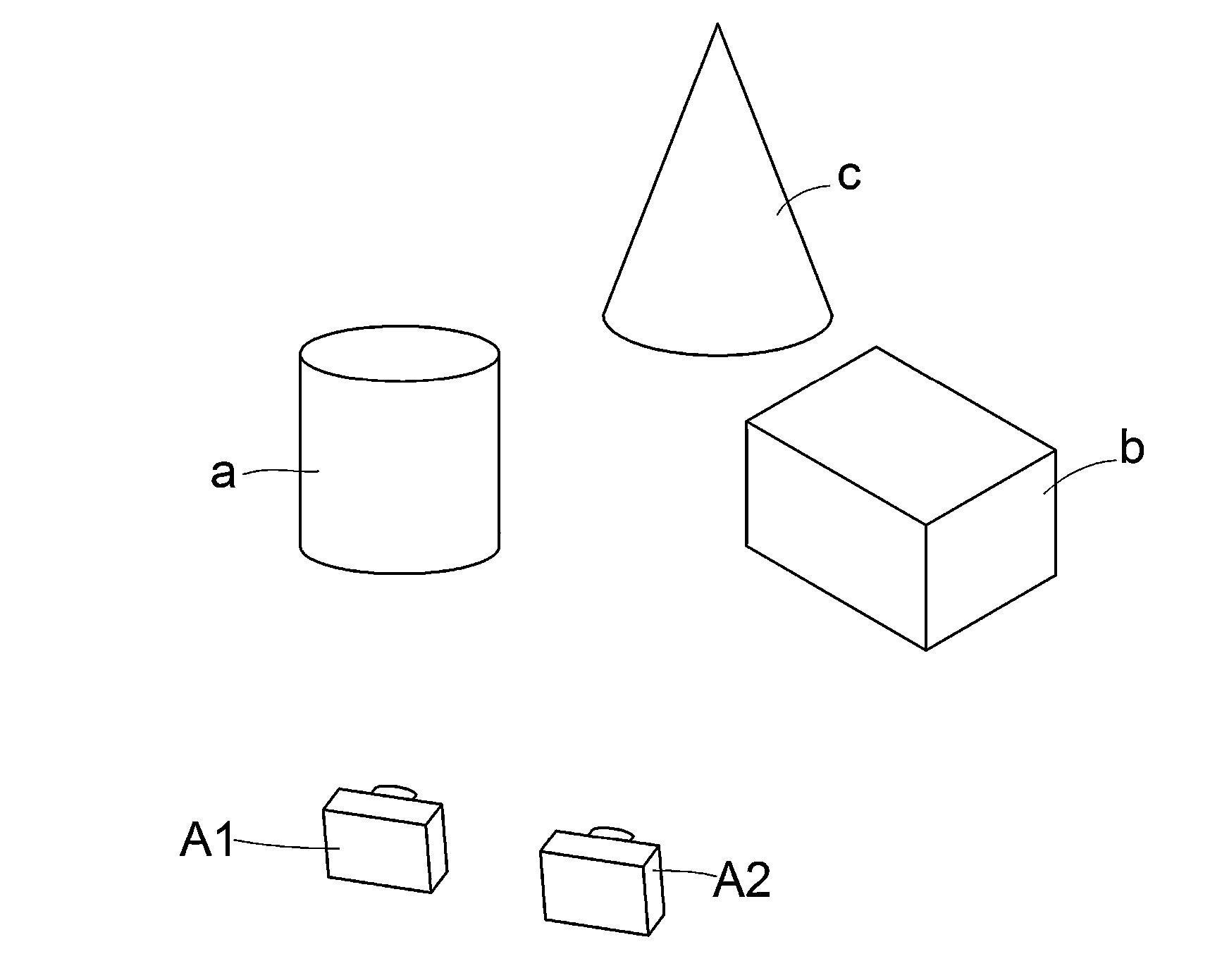
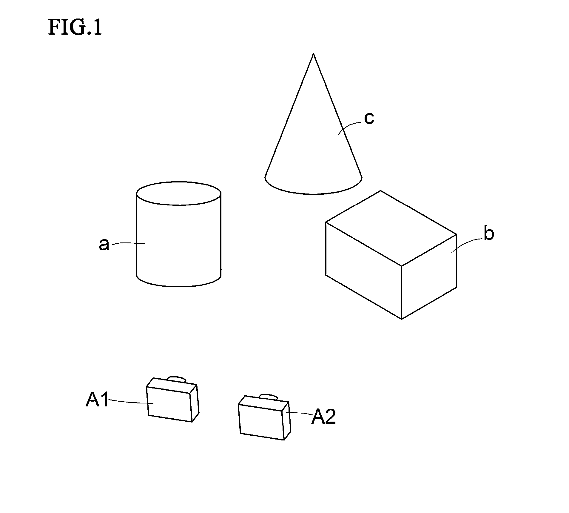
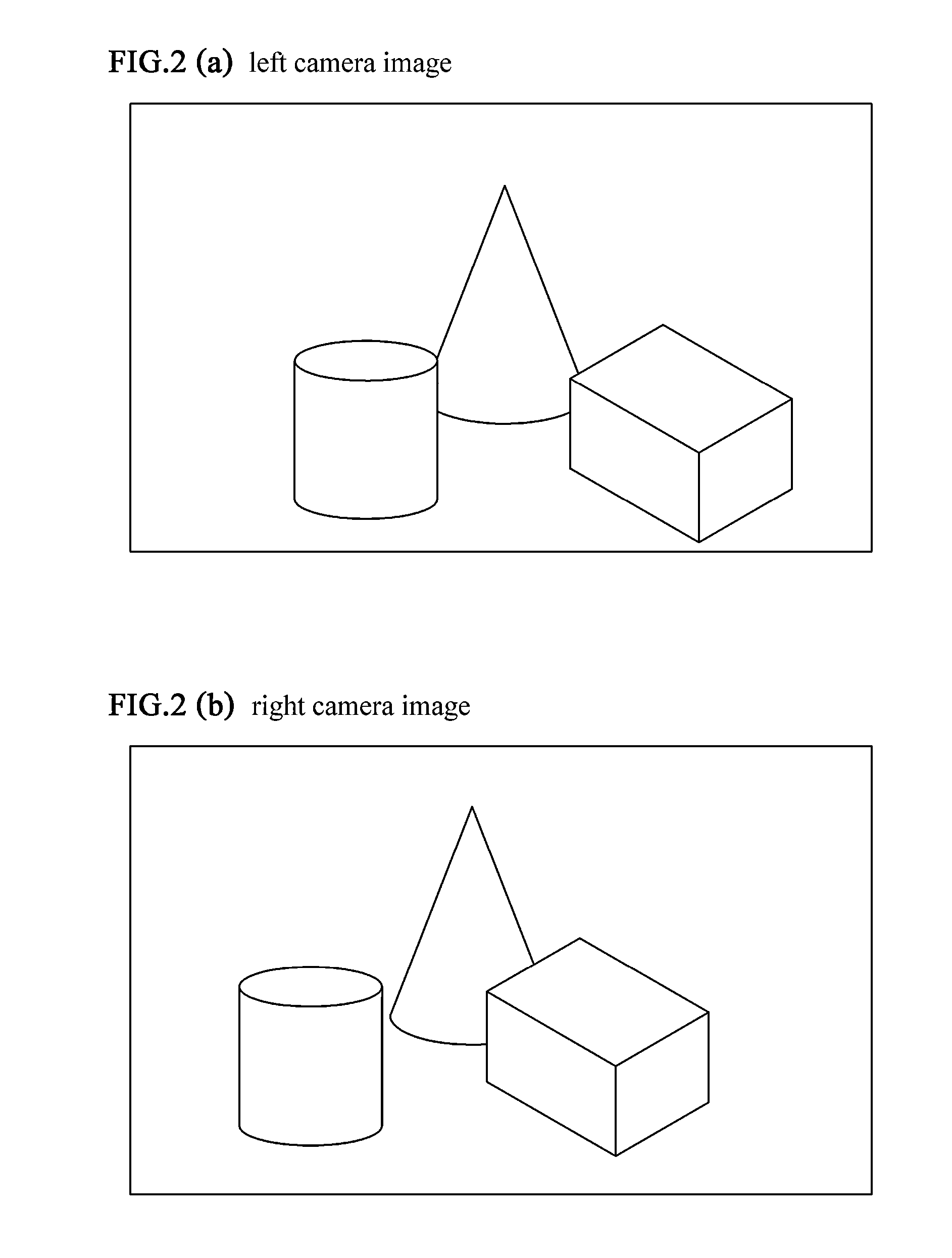
[0032]In the invented image processing method and image processing apparatus, the distance to the objects is estimated in which a sub-pixel disparity cost volume is prepared based on a plurality of parallax images taken by capturing the objects, the noise signals on the cost values are eliminated while considering the edges or boundaries of objects, and then the sub-pixel resolution disparity is computed.

[0033]Here, and similarly in other places, “distance” is denoted as generalized expression. When individual distance to a specific object is to be considered, “distance” is to be taken as “distances to respective objects”, since there are a plurality of objects in an image.

[0034]After the disparity on the images is computed, the distance or depth information will be restored according to the properties of the cameras and their positions. The sub-pixel disparity cost volume will be explained at first.

[0035]The sub-pixel disparity cost volume was obtained by understanding the idea of ...


PUM


Abstract

A sub-pixel disparity cost volume which contains initial cost values of dissimilarity calculated between the pixel values on a standard image of a plurality of parallax images and the interpolated sub-pixel values on the counterpart image or images other than said standard image is prepared for a plurality of parallax images of objects in a three-dimensional structure composed of horizontal, vertical and disparity axes. Noise signals on the calculated cost values in the sub-pixel disparity cost volume are eliminated by using an edge-preserving filter which allocates bigger weights between two cost values whose pixel coordinates have similar pixel values on the standard image, for preserving edges or boundaries of the objects. A sub-pixel disparity is selected, which gives the minimum cost value in the specific disparity range around a previously-given initial pixel-wise or sub-pixel disparity at each pixel coordinate on the standard image. Thus the distance to the objects is estimated from the computed disparity. Precise disparity can be computed by preparing a sub-pixel disparity cost volume and then computing the sub-pixel resolution disparity. Further, the necessary processing time can be reduced by parallel computation manner.

Description

FIELD OF THE INVENTION[0001]This invention is related with an image processing method and an image processing apparatus for estimating the distance between a viewpoint and objects based on a plurality of parallax images that contain disparities.BACKGROUND OF THE INVENTION[0002]Various conventional image processing methods have been employed for estimating the distance between a viewpoint and objects based on several parallax images that were taken from different viewpoints. Computing the distance between a viewpoint and objects is useful and essential for distance measurement tasks in controlling robots and transportation vehicles and estimating the location of items in manufacturing scenes and it therefore has been employed in various forms of applications.[0003]FIGS. 1 and 2 illustrate the disparity obtained from a pair of parallax images that were taken from different viewpoints. FIG. 1 is a perspective view showing a scene including a pillar (a), a rectangular parallelepiped (b)...

Claims


Application Information

Patent Timeline
Patent Type & Authority Applications(United States)
IPC IPC(8): G06T7/00
CPCG06T2207/10012G06T7/0075G01C11/06H04N2013/0081G06T7/593
Inventor MIZUKAMI, YOSHIKIOKADA, KOICHINOMURA, ATSUSHINAKANISHI, SHINYATADAMURA, KATSUMI
Owner MIZUKAMI YOSHIKI
Why Eureka
Try Eureka