
Noise elimination method and noise elimination apparatus

a noise signal and noise elimination technology, applied in the field of noise signal elimination methods and noise elimination apparatuses, can solve the problems of deteriorating resolution power, further deteriorating image quality, and deteriorating image quality, and achieve the effect of eliminating a noise signal mixed into an image signal without deteriorating image quality

Active Publication Date: 2005-06-14
MEGACHIPS
View PDF6 Cites 9 Cited by
  • Summary
  • Abstract
  • Description
  • Claims
  • Application Information

AI Technical Summary

Benefits of technology

[0007]It is an object of the present invention to provide a noise elimination method and a noise elimination apparatus capable of eliminating a noise signal mixed into an image signal without deteriorating the image quality.
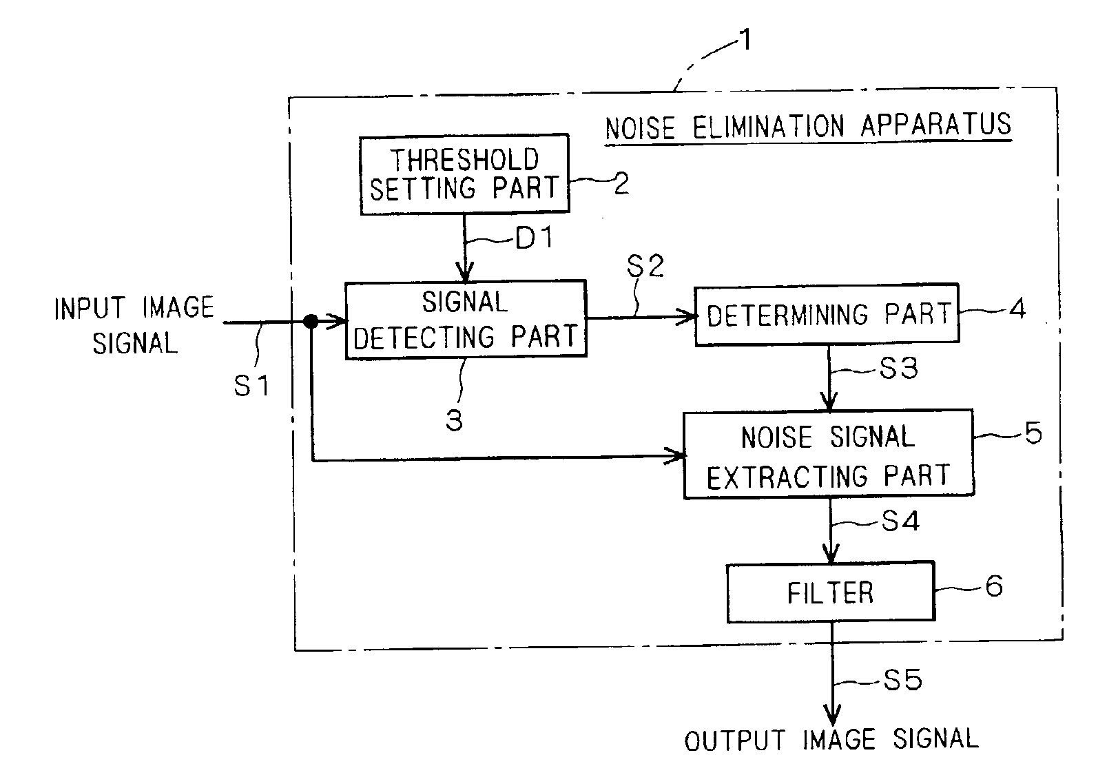
[0016]According to an eighth aspect of the present invention, a noise elimination apparatus eliminates a noise signal mixed into a two-dimensional image signal, and includes a signal detecting part for detecting a zigzag signal in which a differential value between signal levels of two pixels which are adjacent to each other along a horizontal pixel direction or along a vertical pixel direction in the two-dimensional image signal alternately takes a positive value and a negative value; a determining part for determining whether or not the zigzag signal detected by the signal detecting part forms a stripe pattern; a noise signal extracting part for regarding the zigzag signal as a normal image signal when the zigzag signal is determined as forming a stripe pattern by the determining part, while regarding the zigzag signal as a noise signal and extracting the same when the zigzag signal is determined as not forming a stripe pattern; and a filter for eliminating the noise signal from the two-dimensional image signal.
[0024]As described above, according to the noise elimination method and the noise elimination apparatus of the present invention, whether or not the above zigzag signal forms a stripe pattern is determined, and a zigzag signal forming a stripe pattern is regarded as a normal image signal, while a zigzag signal not forming a stripe pattern is regarded as a noise signal. Therefore, detection accuracy of noise signal is improved. Furthermore, since only a noise signal can be selectively eliminated by a filter, it becomes possible to prevent the resolution power from deteriorating due to the noise elimination process.

Problems solved by technology

However, this configuration raises the problem that noise signals get mixed into the image signal captured at the image pickup sensor 105 during the A / D conversion, pixel interpolation and the like processes, to deteriorate the image quality.
If such an image signal including noise signals is subjected to an edge enhancement process, the noise signals are also enhanced, to cause the problem of further deteriorating the image quality.
Such kinds of noise signals may result from the hardware configuration of the A / D converter, or result from interpolating a current pixel using peripheral pixel values in the pixel interpolation process.
However, according to this measure, also the edge portions are blurred as well, leading the problem that the resolution power is deteriorated.

Method used


Image

  • Noise elimination method and noise elimination apparatus
  • Noise elimination method and noise elimination apparatus
  • Noise elimination method and noise elimination apparatus

Examples


Embodiment Construction

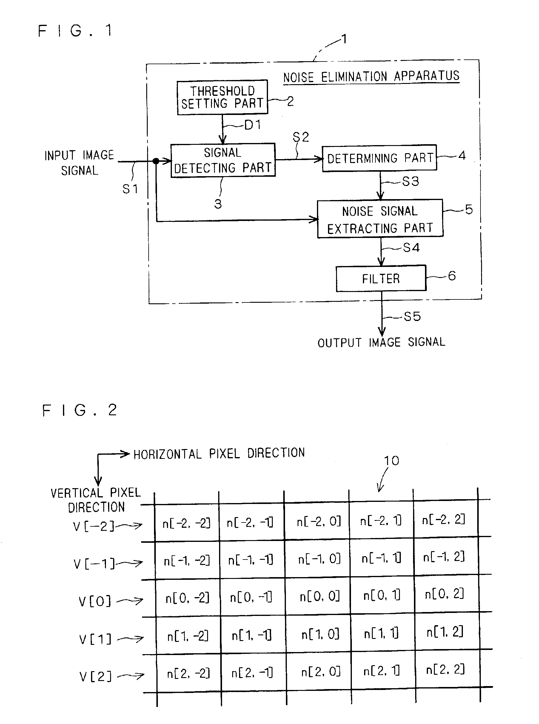
[0038]FIG. 1 is a functional block diagram showing a schematic configuration of a noise elimination apparatus 1 according to an embodiment of the present invention. This noise elimination apparatus 1 includes a signal detecting part 3 for detecting a signal S2 having a zigzag signal level from an input image signal S1 to output the same; a determining part 4 for determining whether or not the zigzag signal S2 is a noise signal; a noise signal extracting part 5 for extracting a noise signal from the image signal S1 based on the determination; and a filter 6 for filtering the extracted noise signal.

[0039]As will be described later, the signal detecting part 3 regards adjacent two pixels as having the same signal level when an absolute differential value of signal level between these tow pixels is not more than a threshold D1 supplied from a threshold setting part 2, and detects the zigzag signal S2 only when the absolute differential value exceeds the threshold D1. This threshold D1 c...


PUM


Abstract

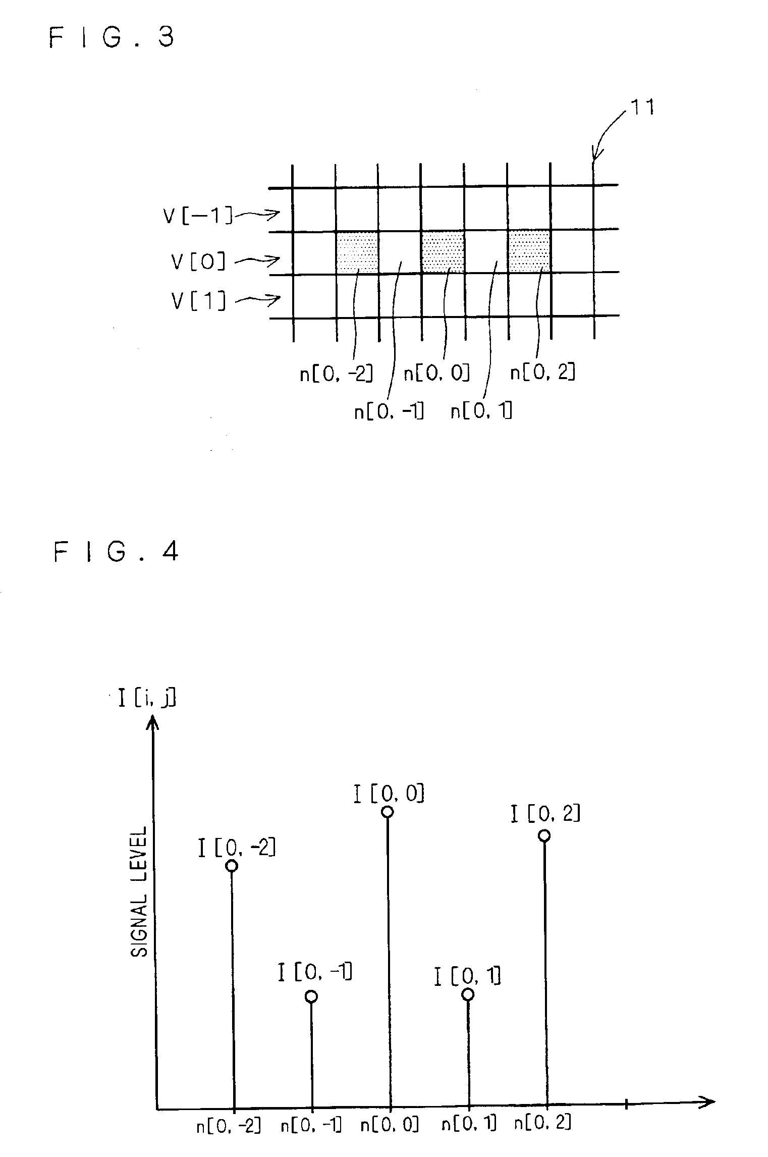
A noise elimination method of the present invention includes the steps of: detecting a zigzag signal in which a differential value between signal levels of two pixels which are adjacent to each other along a horizontal pixel direction or a vertical pixel direction alternately takes a positive value and a negative value (ST2); determining whether or not the zigzag signal forms a stripe pattern (ST3); regarding the zigzag signal as a normal image signal when the zigzag signal is determined as forming a stripe pattern (ST4); regarding the zigzag signal as a noise signal and extracting the same when the zigzag signal is determined as not forming a stripe pattern (ST5); and filtering this noise signal (ST6).

Description

BACKGROUND OF THE INVENTION[0001]1. Field of the Invention[0002]The present invention relates to a noise elimination method and a noise elimination apparatus for detecting and eliminating a noise signal mixed into an image signal captured at an image pickup sensor of a digital camera or the like.[0003]2. Description of the Background Art[0004]FIG. 10 is a block diagram showing a schematic configuration of a common digital still camera. As shown in the figure, in a digital camera 100, an image signal captured by an image pickup sensor 105 such as CCD sensor or CMOS sensor is converted into a digital signal by A / D conversion, and then subjected to a variety of image processings such as pixel interpolation, color space conversion, edge enhancement at an image processing part 106. The image data after subjected to such image processings is then displayed on a LCD (Liquid Crystal Display) 109 or the like, compression-encoded in the JPEG (Joint Photographic Experts Group) format, for exam...

Claims


Application Information

Patent Timeline
IPC IPC(8): H04N5/21G06T5/00G06T5/20H04N1/409H04N5/232H04N101/00
CPCH04N5/21
Inventor MATSUTANI, TAKASHISASAKI, GEN
Owner MEGACHIPS
Learn More