Wirelessly distributed tunnel prediction detecting device, wirelessly distributed tunnel prediction detecting system and wirelessly distributed tunnel prediction detecting method

A technology of advanced forecasting and detection devices, applied in measuring devices, geophysical measurements, instruments, etc., can solve the problems of personnel health hazards, limited manufacturing capacity, and difficulty in bombing bombs

Active Publication Date: 2013-06-26
YUNNAN AEROSPACE ENG GEOPHYSICAL SURVEY INSPECTION
View PDF5 Cites 10 Cited by
  • Summary
  • Abstract
  • Description
  • Claims
  • Application Information

AI Technical Summary

Problems solved by technology

[0005] But, above-mentioned method mainly has the following problems: 1) the manufacturing capacity of the current high-level A / D chip in the world is limited, and when the A / D number of digits increases to a certain degree, it is difficult to further improve the signal-to-noise ratio; 2) when reducing When detecting the signal (source) frequency, the detection distance can be increased, but the detection resolution will be directly reduced; 3) the energy of the source is limited by the amount of explosives, and when excessive explosives are used, there is a danger of blowing up the tunnel; and using Bombing cannons as a source of vibration will increase potential safety hazards and cause serious harm to the health of those who have been engaged in bombing for a long time, etc.

Method used


Image

  • Wirelessly distributed tunnel prediction detecting device, wirelessly distributed tunnel prediction detecting system and wirelessly distributed tunnel prediction detecting method
  • Wirelessly distributed tunnel prediction detecting device, wirelessly distributed tunnel prediction detecting system and wirelessly distributed tunnel prediction detecting method

Examples


Embodiment Construction

[0030] The present invention is described in detail below in conjunction with accompanying drawing:

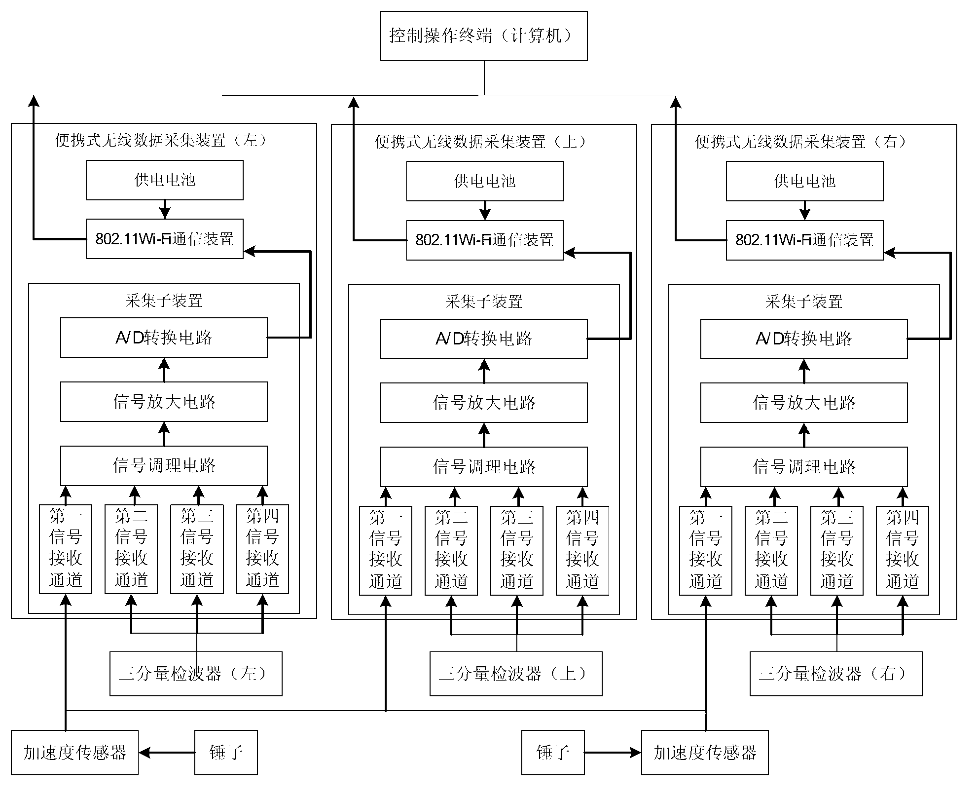
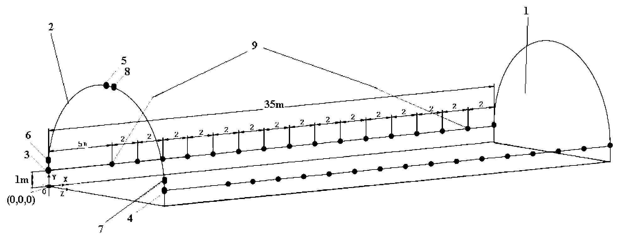
[0031] Such as Figure 1-2 As shown, the present invention provides a wireless distributed tunnel advanced forecast detection device, including a control operation terminal, a wireless data acquisition device, a seismic reflection wave receiving device and a seismic wave excitation device; the output end of the seismic wave excitation device and the seismic reflection wave receiving device The output ends are respectively connected with the input ends of the wireless data acquisition device; the output ends of the wireless data acquisition device are connected with the input ends of the control operation terminal.

[0032] The following introduces the control operation terminal, wireless data acquisition device, seismic reflection wave receiving device and seismic wave excitation device respectively:

[0033] (1) Control operation terminal

[0034] The control operation term...


PUM


Abstract

The invention provides a wirelessly distributed tunnel prediction detecting device, a wirelessly distributed tunnel prediction detecting system and a wirelessly distributed tunnel prediction detecting method. The wirelessly distributed tunnel prediction detecting device comprises a control operation terminal, wireless data acquisition units, earthquake reflected wave receiving devices and earthquake wave excitation devices, wherein output ends of the earthquake wave excitation devices and output ends of the earthquake reflected wave receiving devices are respectively connected with input ends of the wireless data acquisition units, and output ends of the wireless data acquisition units are connected with an input end of the control operation terminal. Via a wireless distributed instrument (24-bit analog to digital) and a hypocenter hammering working mode, high-precision signals can be collected conveniently and quickly, and safety in working can be guaranteed; via a testing mode of a three-mode two-side hammering observation system, elastic wave field data in a three-dimensional space can be effectively obtained to image high-precision three-dimensional image; furthermore, the wirelessly distributed tunnel prediction detecting device has the advantages of simplified structure, low energy consumption, low production cost, simple distribution, high detecting precision, high measuring efficiency and the like.

Description

technical field [0001] The invention belongs to the technical field of tunnel advance forecast detection, and in particular relates to a wireless distributed tunnel advance forecast detection device, system and method. Background technique [0002] At present, the seismic wave (elastic wave) reflection method is one of the most commonly used and most effective methods for tunnel geological advance prediction. Specifically, the seismic wave reflection method is: artificially stimulate the seismic wave, when the seismic wave propagates forward and encounters the wave impedance interface, a part of the signal will be reflected back, and the reflected signal is sometimes called the echo signal; the geophone placed at the rear The signal acquisition system collects and records the echo signals. By analyzing the echo signals, we can understand the engineering properties, positions, occurrences, and scales of engineering geology, hydrogeology, and unfavorable geological bodies in f...

Claims


Application Information

Patent Timeline
Patent Type & Authority Applications(China)
IPC IPC(8): G01V1/00G01V1/147G01V1/18
Inventor 王运生刘浩
Owner YUNNAN AEROSPACE ENG GEOPHYSICAL SURVEY INSPECTION
Why Eureka
Try Eureka