Supercharge Your Innovation With Domain-Expert AI Agents!

Generating tracking control output signals for compensating tracking error signals

a tracking control and output signal technology, applied in the field of optical disk drives, can solve the problems of inability to precisely inability to accurately count the number of tracks, and shape of sine waves that sometimes produce erroneous te,

Inactive Publication Date: 2005-01-13
LITE ON TECH CORP
View PDF3 Cites 0 Cited by
  • Summary
  • Abstract
  • Description
  • Claims
  • Application Information

AI Technical Summary

Benefits of technology

The present disclosure provides systems and methods for tracking of control and error signals in optical disk drives. In some embodiments, successive square waves are generated as a tracking control output signal. A tracking error signal is generated as a function of an offset correction factor and, also, as a function of the tracking control output signal.

Problems solved by technology

Moreover, in an optical disk drive adapted for counting the number of tracks that laser beams traverse based on the tracking error signal, if any offset exists in the tracking error signal as described above, it is impossible to precisely count the number of tracks.
Unfortunately, the shape of the sine wave sometimes produces erroneous TE.
Thus, a heretofore-unaddressed need exists in the industry to address the aforementioned deficiencies and inadequacies.

Method used


Image

  • Generating tracking control output signals for compensating tracking error signals
  • Generating tracking control output signals for compensating tracking error signals
  • Generating tracking control output signals for compensating tracking error signals

Examples


Embodiment Construction

Reference is now made in detail to the description of the embodiments as illustrated in the drawings. While several embodiments are described in connection with these drawings, there is no intent to limit the invention to the embodiment or embodiments disclosed herein. On the contrary, the intent is to cover all alternatives, modifications, and equivalents.

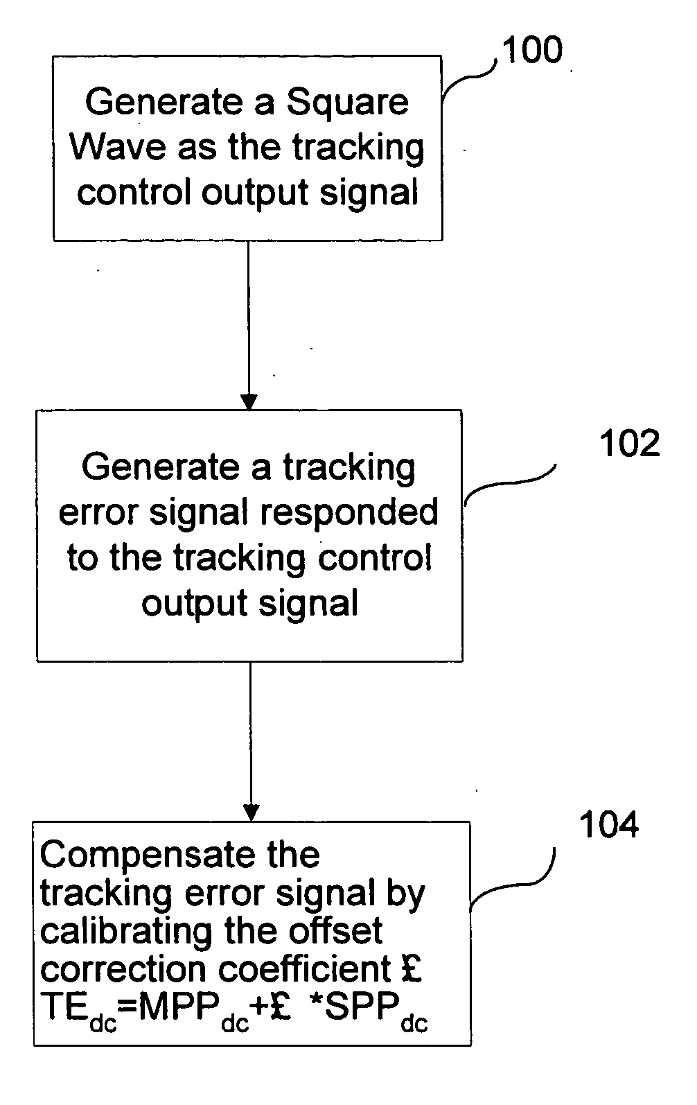
While sine waves are typically used to as tracking control signals in optical disk drives, the inherent characteristics of sine waves sometimes produce erroneous results during tracking in optical disk drives. By using square waves, rather than sine waves, as tracking control signals, more reliable tracking is possible due to the inherent characteristics of square waves. FIGS. 4 through 6 show several embodiments in which the tracking control is improved by the use of square waves.

FIG. 4 is a flowchart showing an embodiment of a process for compensating a tracking error signal in an optical disk drive. As shown in FIG. 4, some...


PUM

PropertyMeasurementUnit
timeaaaaaaaaaa
reflection characteristicsaaaaaaaaaa
sizeaaaaaaaaaa

Abstract

The present disclosure provides systems and methods for tracking of control and error signals in optical disk drives. Successive square waves are generated as a tracking control output signal, and a tracking error signal is generated as a function of both the tracking control output signal and an offset correction factor. Due to the characteristics of the square wave, more reliable tracking is possible by the use of the square wave.

Description

FIELD OF INVENTION The present disclosure generally relates to optical disk drives and, more particularly, to tracking of control and error signals in optical disk drives. BACKGROUND As shown in FIG. 1(a), an optical disk 2 comprises lands 6 and grooves 4 that contain recorded information. Optical disk drives read and write data from optical disks 2 by irradiating the optical disk with a laser. Due to the different reflection characteristics between the lands 6 and grooves 4, the content of the information written on the optical disk 2 may be determined by the different reflection characteristics. The size of the lands 6 and grooves 4 on the optical disk 2 are fairly small. Thus, in order to properly read data from, and write data to, optical disks, the laser is focused on a particular track. The focusing and tracking of the laser often involves processes for generating and detecting tracking error signals. In an example optical pickup module 1, as shown in FIG. 2, an optical pi...

Claims


Application Information

Patent Timeline
Patent Type & Authority Applications(United States)
IPC IPC(8): G11B7/00G11B7/09
CPCG11B7/094
Inventor JEN-YU, HSUHSIANG-YI, FUTUN-CHIEH, LEEFU-HSIANG, CHENYAO-CHOU, TSAI
Owner LITE ON TECH CORP
Features
  • R&D
  • Intellectual Property
  • Life Sciences
  • Materials
  • Tech Scout
  • Unparalleled Data Quality
  • Higher Quality Content
  • 60% Fewer Hallucinations
Learn More