Developing apparatus

a technology of developing apparatus and developing electrode, which is applied in the direction of electrographic process apparatus, instruments, optics, etc., can solve the problems of image failure, image failure, and large image density portion in the resultant image, and achieves excellent environmental adaptability, simple process, and stably used

Inactive Publication Date: 2005-01-13
CANON KK
View PDF6 Cites 27 Cited by
  • Summary
  • Abstract
  • Description
  • Claims
  • Application Information

AI Technical Summary

Benefits of technology

[0021] An object of the present invention is to provide a developing apparatus which is provided through a simple process, excellent in environmental adaptability, and stably used until its operating life.
[0022] Another object of the present invention is to provide a developing apparatus capable of reducing an occurrence of image failure causing an increase in image density at an image trailing end portion.
[0023] A further object of the present invention is to provide a developing apparatus capable of suppressing current leakage to an image bearing member along the surface of a developer regulation member.

Problems solved by technology

In the developing apparatus effecting development by the oscillation electric field, such a problem that image failure called “downstream concentration” is caused to occur has been known.
When such an image is formed, image failure such that a larger image density portion is observed in the resultant image is caused to occur.
However, this method is not sufficient to prevent the downstream concentration.

Method used


Image

  • Developing apparatus
  • Developing apparatus
  • Developing apparatus

Examples


embodiment 1

[0047] (Embodiment 1)

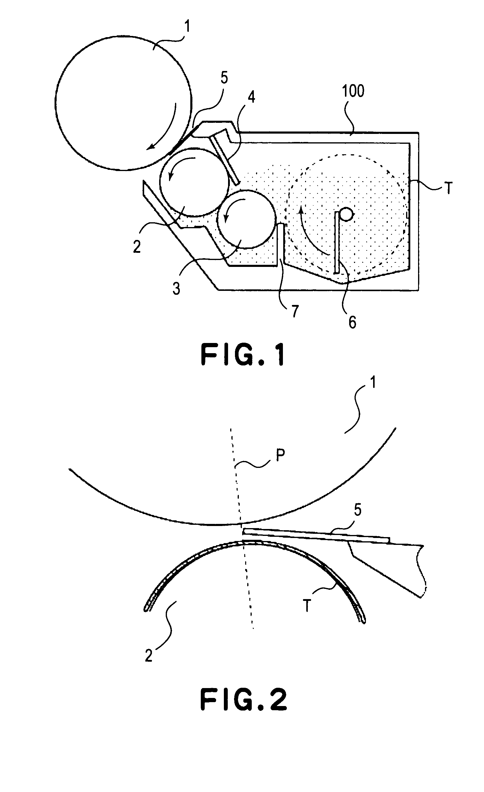
[0048] A developing apparatus according to this embodiment is shown in FIG. 1.

[0049] A developing apparatus 100 shown in FIG. 1 includes a developing device of a nonmagnetic monocomponent noncontact development type.

[0050] With respect to structural members other than the developing apparatus for an image forming apparatus, those for the image forming apparatus shown in FIG. 14 are applicable, so that explanation therefor will be omitted.

[0051] Hereinafter, the developing apparatus 100 will be described in detail.

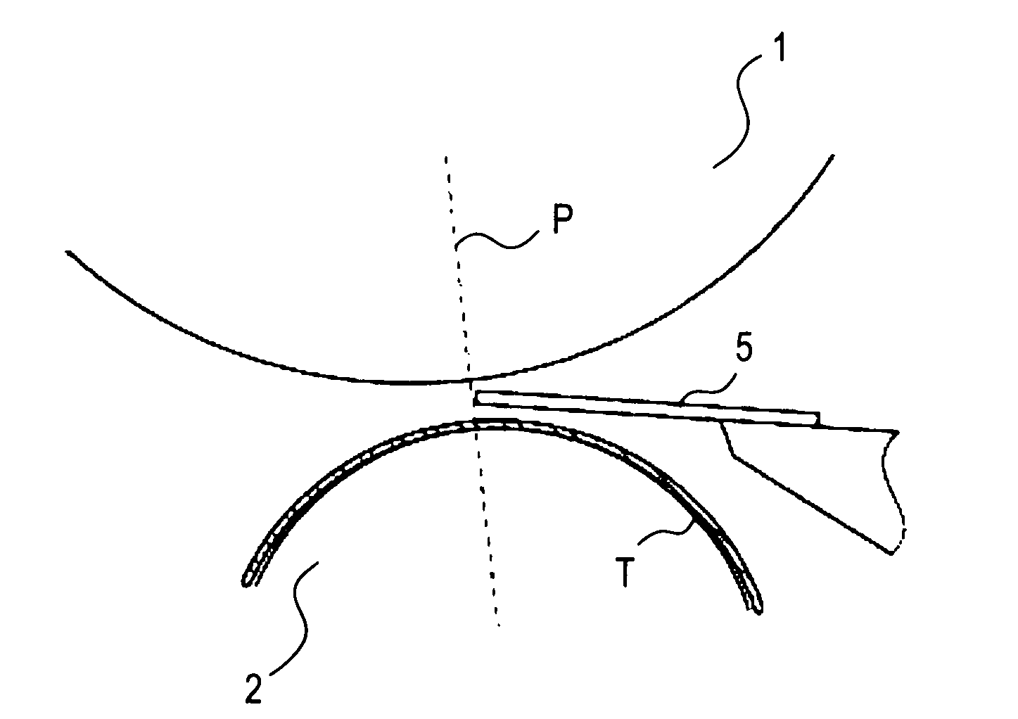
[0052] In FIG. 1, there are present a photosensitive drum 1 as an image bearing member, a developing roller (developing sleeve) 2 as a developer carrying member, a developer supply / scraping roller 2 a a developer supply member, a toner amount regulation member 4, a jumping developer control member 5 as a jumping developer regulation member for regulating an area wherein developer is caused to jump, toner T as nonmagnetic monocomponent developer, and...

embodiment 2

[0087] (Embodiment 2)

[0088]FIG. 10 shows a schematic structural view of a developing apparatus in this embodiment.

[0089] With respect to structures and operations, members or means identical to those used in Embodiment 1 are represented by identical reference numerals or signs and explanation therefor is omitted.

[0090] As features of Embodiment 2, a jumping developer control member51 is an elastic sheet and is disposed so as not to contact a toner coating layer on the developing roller 2 in the developing zone. Further, the jumping developer control member 51 is in contact with the photosensitive drum 1 in the developing zone.

[0091] The jumping developer control member 51 is required to be accurately inserted into the SD gap of 300 μm. In this embodiment, the elastic sheet is used as the jumping developer control member 51 is brought into contact with the photosensitive drum 1 under pressure, whereby it becomes possible to accurately set the free end position of the jumping devel...

embodiment 3

[0096] (Embodiment 3)

[0097]FIG. 12 shows a schematic structural view of a developing apparatus in this embodiment.

[0098] With respect to structures and operations, members or means identical to those used in Embodiment 1 are represented by identical reference numerals or signs and explanation therefor is omitted.

[0099] As features of Embodiment 2, a jumping developer control member 52 is disposed toward point A, on the line P connecting the rotation centers of the photosensitive drum 1 and the developing roller 2, located within the photosensitive drum 1. By doing so, the jumping developer control member 53 is pressed against the photosensitive drum 1 surface. In this embodiment, as the jumping developer control member 52, an elastic sheet member comprising a 500 μm-thick PET (polyethylene terephthalate) film is used.

[0100] Effects of this embodiment will be described.

[0101] The jumping developer control member 52 is required to be accurately inserted into the SD gap of 300 μm. ...


PUM


Abstract

A developing apparatus includes a developer carrying member, disposed opposite to an image bearing member, for carrying developer which is caused to jump from the developer carrying member to the image bearing member to develop an electrostatic latent image formed on said image bearing member by creating an oscillation electric field between the image bearing member and the developer carrying member at an opposing portion where the image bearing member and the developer carrying member are opposed to each other; and a jumping developer regulation member for regulating an area in which the developer is caused to jump in the opposing portion. The jumping developer regulation member is disposed apart from the developer carried by the developer carrying member and is an insulating member or an electrically floating member.

Description

FIELD OF THE INVENTION AND RELATED ART [0001] The present invention relates to a developing apparatus in which an oscillation electric field is created between an image bearing member and a developer carrying member at an opposing portion where the image bearing member and the developer carrying member are opposed to each other, whereby developer is caused to jump from the developer carrying member to the image bearing member to effect development. The developing apparatus is suitable for the use of a nonmagnetic monocomponent developer and is preferably used in an image forming apparatus utilizing an electrophotographic scheme or an electrostatic recording scheme. [0002] As a laser beam printer or a copying machine, an image forming apparatus using an electrophotographic process as shown in FIG. 14 has been conventionally proposed. A basic operation of the image forming apparatus will be described hereinbelow. [0003] An electrophotographic photosensitive member 11 ordinarily having...

Claims


Application Information

Patent Timeline
Patent Type & Authority Applications(United States)
IPC IPC(8): G03G15/08G03G15/06
CPCG03G2215/0619G03G15/0813G03G15/0808G03G15/081G03G15/0849G03G21/181G03G21/1814
Inventor KAWAMURA, TAKESHINAKAGAWA, KEN
Owner CANON KK
Why Eureka
Try Eureka