Sprocket for chain

a chain and socket technology, applied in the direction of driving chains, gearing, hoisting equipment, etc., can solve the problems of noise generation, and achieve the effect of reducing the magnitude of the pulse motion of the roller chain or the bushing chain due to polygonal motion, reducing vibration and reducing the speed change speed of the roller chain or the bushing chain

Inactive Publication Date: 2005-01-13
TSUBAKIMOTO CHAIN CO
View PDF6 Cites 14 Cited by
  • Summary
  • Abstract
  • Description
  • Claims
  • Application Information

AI Technical Summary

Benefits of technology

[0011] At the engagement between a sprocket and a roller chain or a bushing, while a preceding roller or bushing is engaged with the sprocket in a tooth groove, the following roller or bushing engages with a front tooth surface. At this time the center of the preceding roller or bushing and the center of the following roller or bushing are positioned on the same horizontal line. Therefore, the magnitude of pulse motion of the roller chain or bushing chain due to polygonal motion can be further reduced. As a result, the vibration of the roller chain or bushing chain is reduced, and the speed change of the roller chain or bushing chain is also reduced. Furthermore, since the vibration of the roller chain or bushing chain is reduced, a reduction of noise can be realized, and the tension change is also reduced, thereby increasing the life of the roller chain or bushing chain.
[0012] Where the tooth gap bottom circle diameter of the sprocket is smaller than the tooth gap bottom circle diameter for the ISO tooth form, while each of rollers or bushings is moved while rolling in the tooth grooves as the sprocket rotates, the position of the roller or bushing in the tooth groove of the sprocket is moved from a front tooth surface to a rear tooth surface. At the location of disengagement between the sprocket and the chain, when a following roller or bushing is engaged with a rear tooth surface, the preceding roller or bushing is smoothly disengaged from a rear tooth surface of a preceding tooth, and thereby smoothly disengaged from the sprocket.

Problems solved by technology

The pulsing in turn vibrates the roller chain 61, which causes generation of noise.
However, the roller chain sprocket of Japanese Patent No. 2002-514287 leaves room for further improvement in the reduction of pulse motion of the roller chain due to polygonal motion.

Method used


Image

  • Sprocket for chain
  • Sprocket for chain
  • Sprocket for chain

Examples


second embodiment

[0039] In the second embodiment, illustrated in FIGS. 5, 6 and 7, teeth 25 are separated by tooth grooves 24, in which facing tooth surfaces 22a and 22b are continuously connected to each other by tooth gap bottom portion 23.

[0040] A front tooth surface 22a and a rear tooth surface 22b are symmetrical on the right and left sides of the center line x of the tooth 25. Each of the tooth surfaces 22a and 22b has a substantially convex curve. Furthermore, the tooth gap bottom portion 23 is arc-shaped, with an arc radius ri23. The tooth surface 22a and tooth surface 22b, both of which have a substantially convex curve, are smoothly and continuously connected to each other by the tooth gap bottom portion 23.

first embodiment

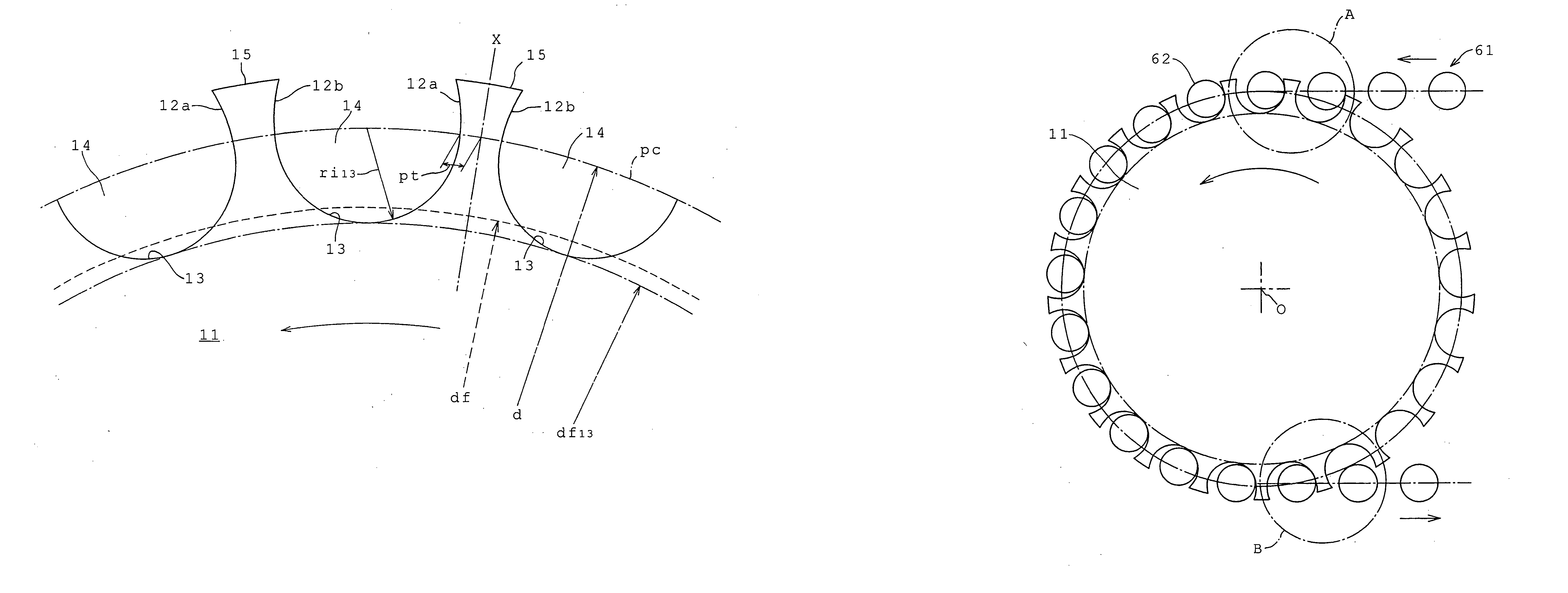
[0041] As in the case of the first embodiment, in the embodiment shown in FIG. 5, the tooth form in the sprocket has portions, on the tooth head side of the pitch circle pc, where distances from the center line x to the front tooth surface 22a, and to a rear tooth surface 22b, are larger than the distance pt in the pitch circle pc.

[0042] The diameter df23 of the tooth gap bottom circle is also smaller than the diameter df of a tooth gap bottom circle in an ISO tooth form. That is, df23

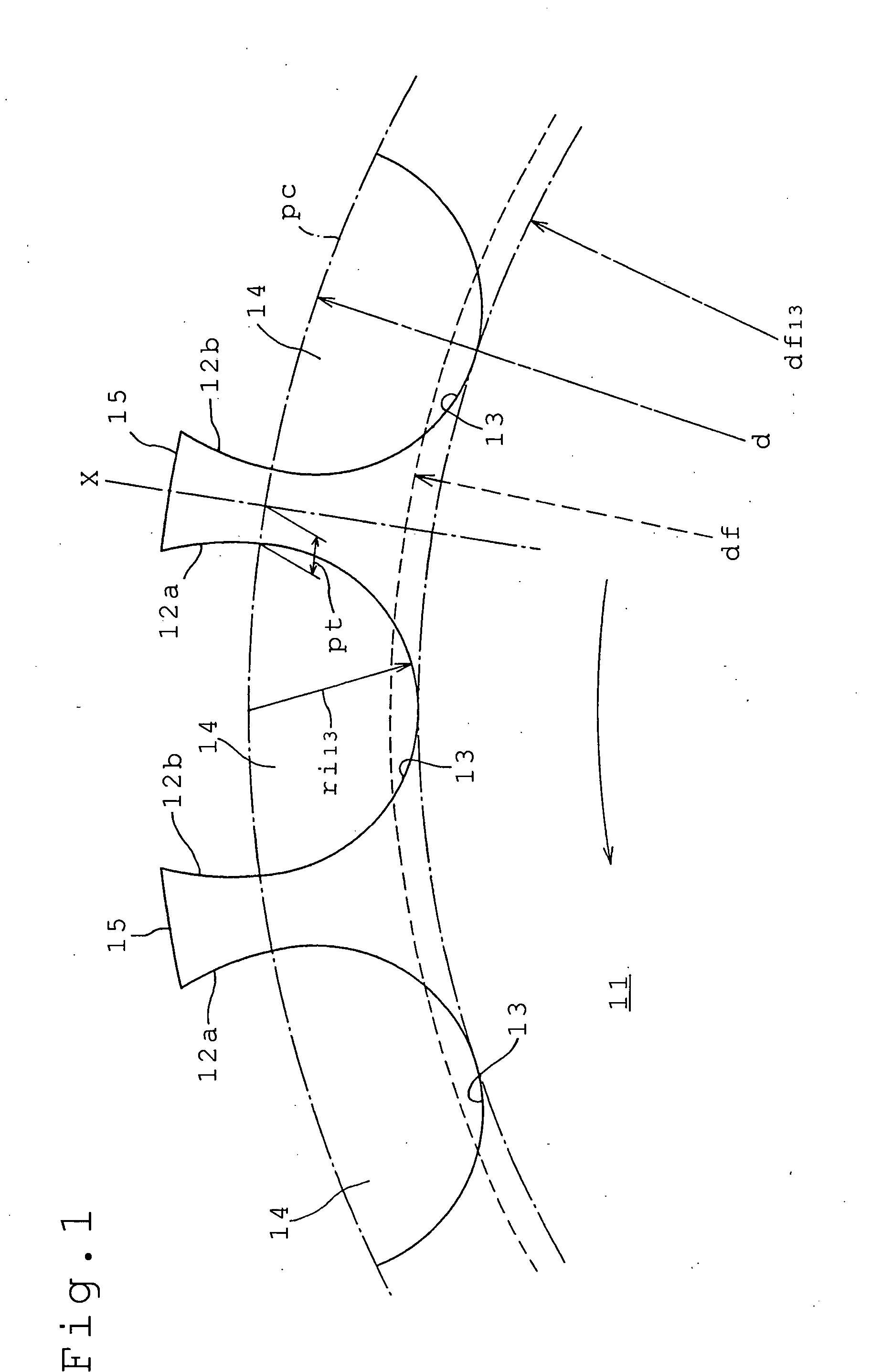
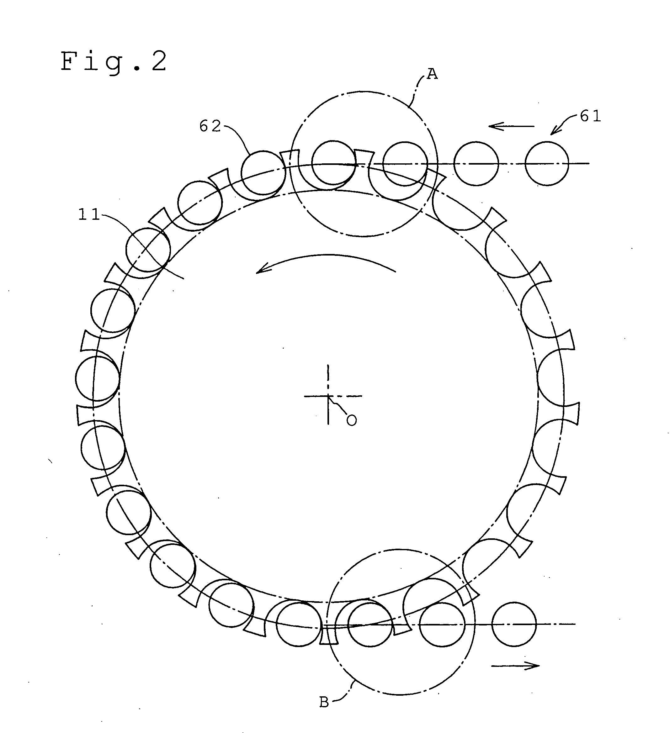
[0043] As shown in FIG. 6, while a preceding roller 62a is engaged with the sprocket 21 in a tooth groove 24, the following roller 62b is engaged with a front tooth surface 22a. As in the case of the first embodiment, the center of the preceding roller 62a and the center of the following roller 62b are positioned on the same horizontal line. Furthermore, altho...

third embodiment

[0046] In the third embodiment, illustrated in FIGS. 8, 9, and 10, teeth 35 are separated by tooth grooves 34, in which facing tooth surfaces 32a and 32b are continuously connected to each other by tooth gap bottom portion 33.

[0047] A front tooth surface 32a and a rear tooth surface 32b are symmetrical on the right and left sides of the center line x of the tooth 35. In this embodiment, the faces of the teeth outside the pitch circle are linear in cross section, and the tooth surfaces 32a and 32b are in the form of substantially parallel planes. Furthermore, the tooth gap bottom portion 33 is arc-shaped, with an arc radius ri33. The tooth surface 32a and tooth surface 32b, both of which are substantially planar, are smoothly and continuously connected to each other by the tooth gap bottom portion 33.

[0048] In this case, the tooth form in the sprocket has portions, on the tooth head side of the pitch circle pc, where distances from the center line x to the front tooth surface 32a, a...


PUM


Abstract

In a sprocket for a roller chain, the tooth form is such that the distance between the tooth center line and a part of the front tooth surface, at a location on the tooth head side of the pitch line, is greater than the distance between the tooth center line and the front surface of the tooth along the pitch line. The diameter of the tooth gap bottom circle is smaller than the diameter of a tooth gap bottom circle in a sprocket having an ISO tooth form for the same chain.

Description

FIELD OF THE INVENTION [0001] This invention relates to a sprocket for a chain in which plural teeth are formed by tooth grooves each of which has facing tooth faces connected continuously to each other by a tooth gap bottom, and in which rollers or bushings engage with the tooth grooves. BACKGROUND OF THE INVENTION [0002] Tooth forms for roller chain sprockets, referred to as ISO tooth forms, are defined in ISO 606: 1994 (E). FIG. 17 shows an ISO tooth form, and FIG. 18 illustrates the engagement between a roller chain and a sprocket having the ISO tooth form shown in FIG. 17. [0003] In the ISO tooth form shown in FIG. 17, when the chain pitch is p, the pitch circle diameter is d, the roller outer diameter is d1, the radius of the arc of the tooth gap bottom portion is ri, the tooth surface radius is re, the diameter of the tooth gap bottom is df, and the number of sprocket teeth is z, the relationships of these parameters are defined by the following expressions from ISO 606: 1994...

Claims


Application Information

Patent Timeline
Patent Type & Authority Applications(United States)
IPC IPC(8): F16G13/02F16G13/06F16H55/08F16H55/30
CPCF16H55/30
Inventor KUBO, AIZOHSONODA, MASATOSHISAITOH, TOYONAGA
Owner TSUBAKIMOTO CHAIN CO
Why Eureka
Try Eureka