Method for correction of relative object-detector motion between successive views

a technology of motion correction and object detection, applied in the field of imaging, can solve the problems of difficult to position the rotation axis, the center of the detector's fov, and the difficulty of holding the microcapillary tube stationary while rotating

Inactive Publication Date: 2005-01-13
VISIONGATE
View PDF79 Cites 175 Cited by
  • Summary
  • Abstract
  • Description
  • Claims
  • Application Information

AI Technical Summary

Problems solved by technology

Owing to the extremely small sizes of the components, it can be quite difficult to position the axis of rotation (typically coincident with the central axis of the microcapillary tube) in the center of the detector's FOV.
It is further very difficult to hold the mic

Method used


Image

  • Method for correction of relative object-detector motion between successive views
  • Method for correction of relative object-detector motion between successive views
  • Method for correction of relative object-detector motion between successive views

Examples


Embodiment Construction

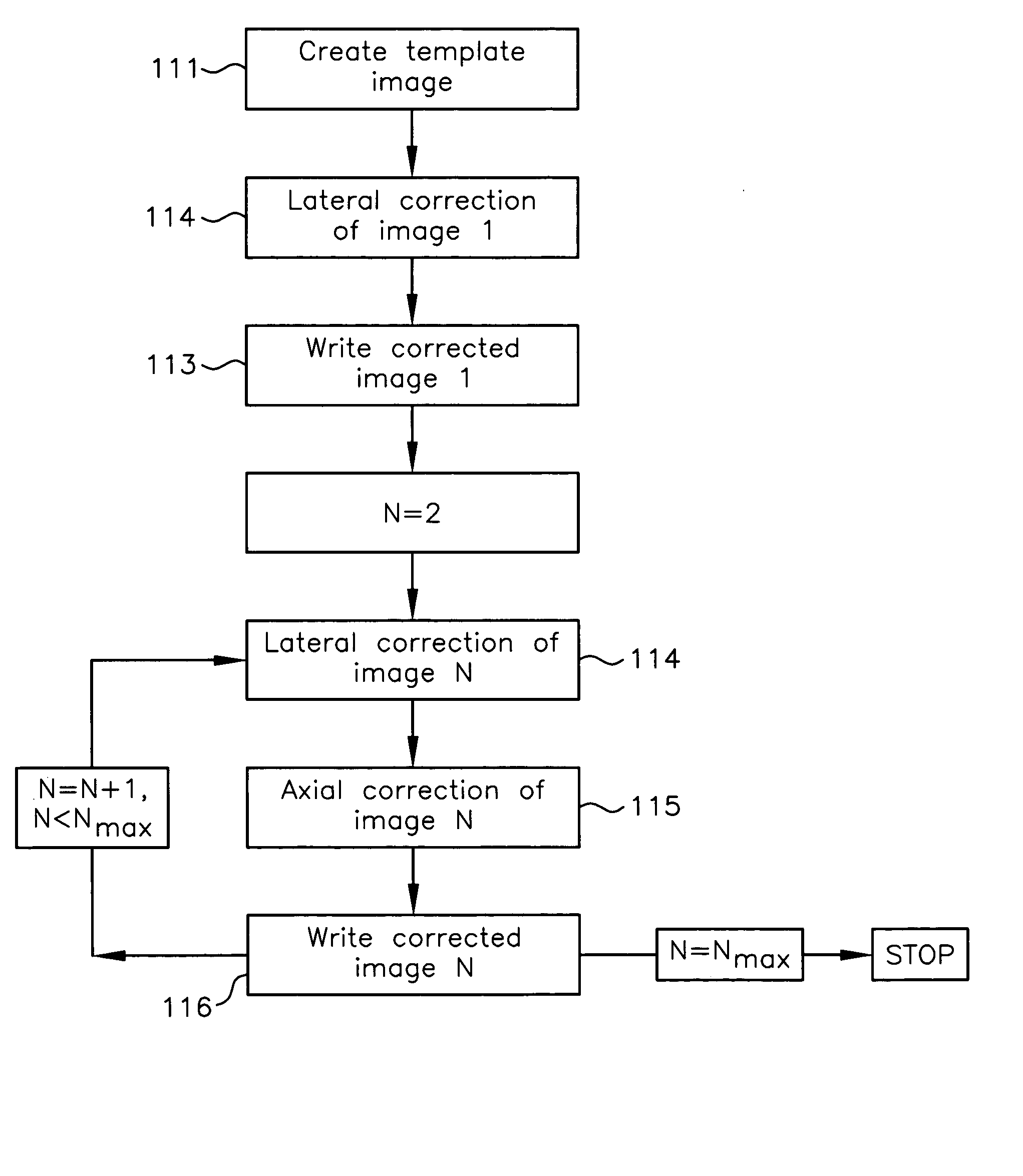
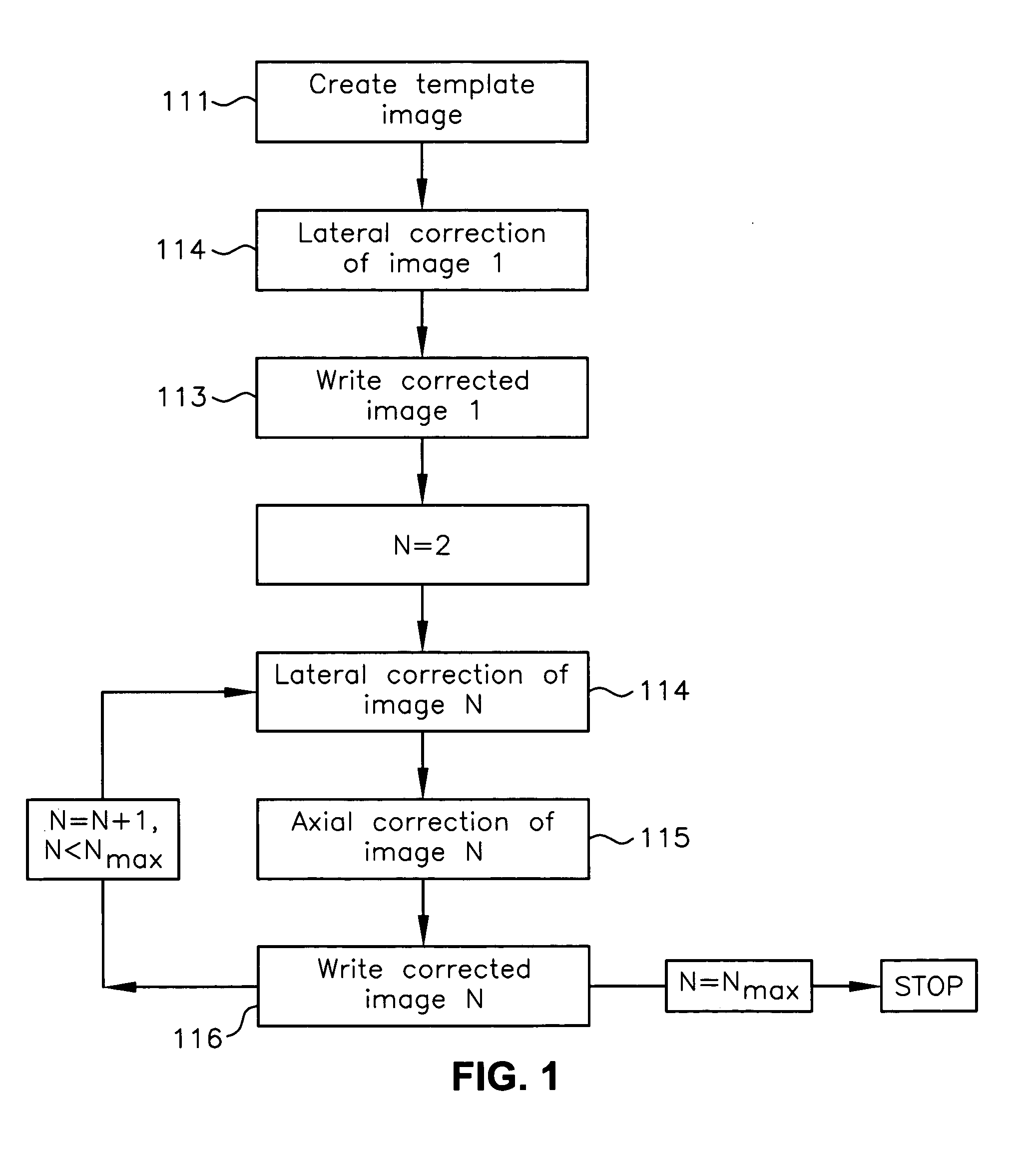
[0021] The invention is described herein with respect to specific examples relating to biological cells, however, it will be understood that these examples are for the purpose of illustrating the principals of the invention, and that the invention is not so limited. Although the present invention may be employed in other types of imaging systems, such as, for example, X-ray computed tomography (CT) imaging, for concreteness of description the following disclosure is directed toward the invention in the environment of an optical projection tomographic microscopy (OPTM) system.

[0022] In the discussion that follows, the following assumptions are used when providing numerical examples:

[0023] 1. Each image consists of an array, 640 pixels wide by 480 pixels high;

[0024] 2. Each pixel contains a single 8-bit (gray level 0 to 255) brightness value;

[0025] 3. With reference to an OPTM using a microcapillary tube, the tube axis is parallel to the shorter axis (480 pixels);

[0026] 4. With r...


PUM


Abstract

Registration correction for optical tomographic imaging in three dimensions. An object of interest is illuminated to produce an image. A lateral offset correction value is determined for the image. An axial offset correction value is determined for the image. The lateral offset correction value and the axial offset correction value are applied to the image to produce a corrected file image.

Description

RELATED APPLICATIONS [0001] This application is a continuation-in-part (CIP) of co-pending U.S. patent application Ser. No. 10 / 126,026, filed Apr. 19, 2002, of Nelson, entitled “Variable Motion Optical Tomography of Small Objects,” which is incorporated herein by this reference.FIELD OF THE INVENTION [0002] The present invention relates to imaging and, more particularly, to detection of and correction for relative object-detector motion in an imaging system where, typically, successive views from different positions are acquired, each view representing a two-dimensional projection or pseudo-projection of the three-dimensional object. BACKGROUND OF THE INVENTION [0003] An optical projection tomographic microscopy (OPTM) is suitable for high-resolution imaging of a microscopic object, such as a biological cell and its nucleus, which are embedded in a fluid medium and contained within a microcapillary tube having inner and outer diameters of 40 microns and 150 microns, respectively. An...

Claims


Application Information

Patent Timeline
IPC IPC(8): G01N21/17A61B10/00G01N15/14G01N21/21G01N21/47
CPCG01N15/1468G06T2211/421G01N15/1475G01N21/05G01N21/4795G01N2015/1006G01N2015/1075G01N2021/0346G01N2021/1787G01N2201/0813G01N2223/612G02B21/26G02B21/365G06T11/005G06T11/006G06T2211/412G01N15/147
Inventor RAHN, JOHN RICHARDNELSON, ALAN C.
Owner VISIONGATE
Why Eureka
Try Eureka