Cervical distraction device

a cervical distraction and device technology, applied in the field of cervical distraction devices, can solve the problems of preventing efficient control of the force, mismatched cervical distraction force application, and oversized conventional motors of vertebral distraction machines, so as to improve the amount of control and eliminate flexibility

Active Publication Date: 2005-01-13
NORTH AMERICAN MEDICAL CORPORTAION
View PDF4 Cites 14 Cited by
  • Summary
  • Abstract
  • Description
  • Claims
  • Application Information

AI Technical Summary

Benefits of technology

[0010] A cervical traction device having a base, a cervical force application member, and a motor is provided to apply a force to a cervical vertebra of a person. The cervical force application member is mounted such that it is movable relative to the base, and the motor is operably attached to the cervical force application member by

Problems solved by technology

The primary problem with this method of cervical distraction is that it provides an indirect, flexible power transfer linkage between the motor applying force and the patient's head.
This flexible linkage prevents efficient control of the force.
Additionally, the forces required for cervical traction are much less than those required for lower vertebral traction; therefore, the conventional motor associated with vertebral dist

Method used


Image

  • Cervical distraction device
  • Cervical distraction device
  • Cervical distraction device

Examples


Embodiment Construction

[0027] In the following detailed description of the preferred embodiments, reference is made to the accompanying drawings, which form a part hereof, and in which is shown by way of illustration specific preferred embodiments in which the invention may be practiced. These embodiments are described in sufficient detail to enable those skilled in the art to practice the invention, and it is understood that other embodiments may be utilized and that logical software, electrical, mechanical, structural, and material changes may be made without departing from the spirit or scope of the invention. To avoid detail not necessary to enable those skilled in the art to practice the invention, the description may omit certain information known to those skilled in the art. The following detailed description is, therefore, not to be taken in a limiting sense, and the scope of the present invention is defined only by the appended claims.

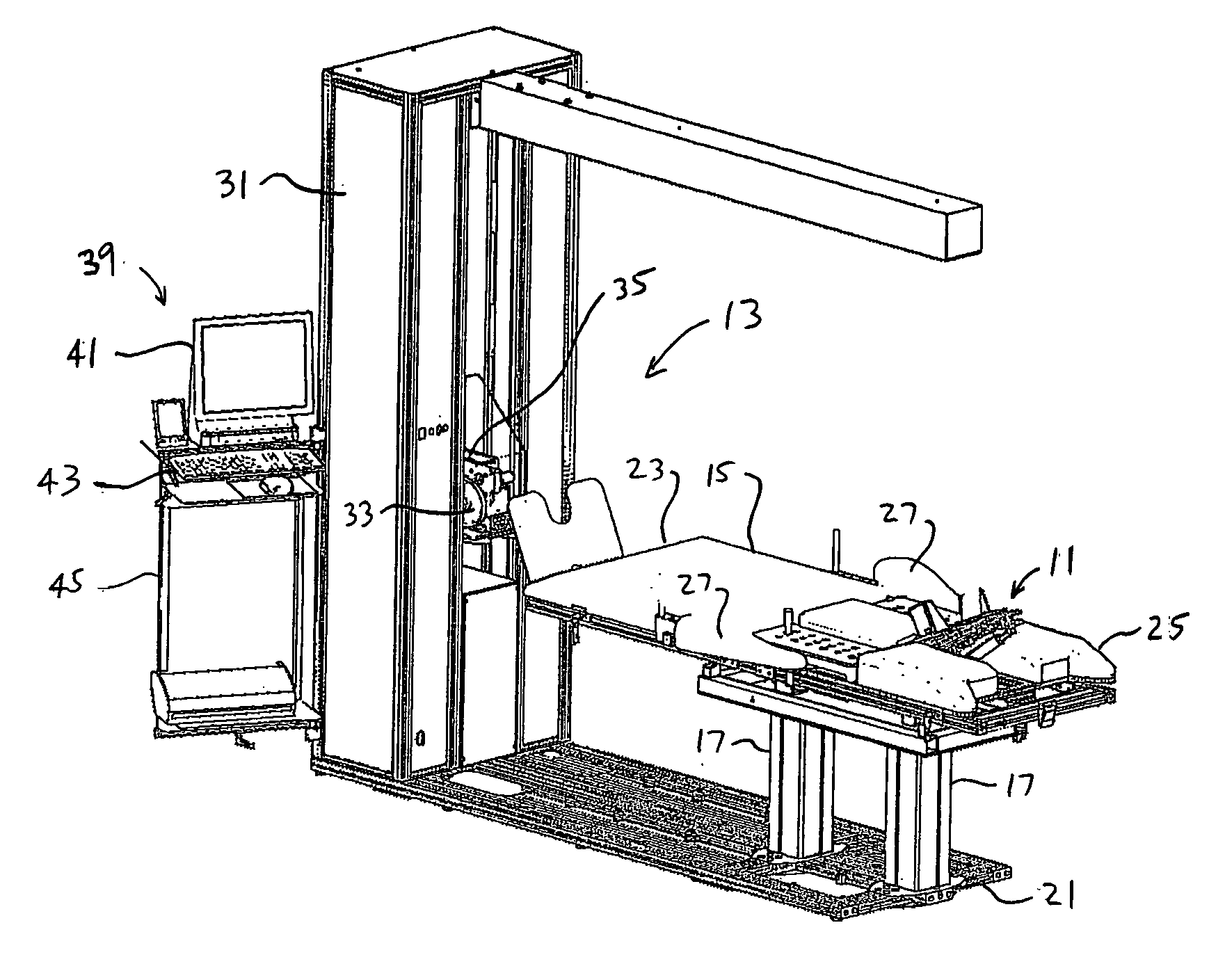
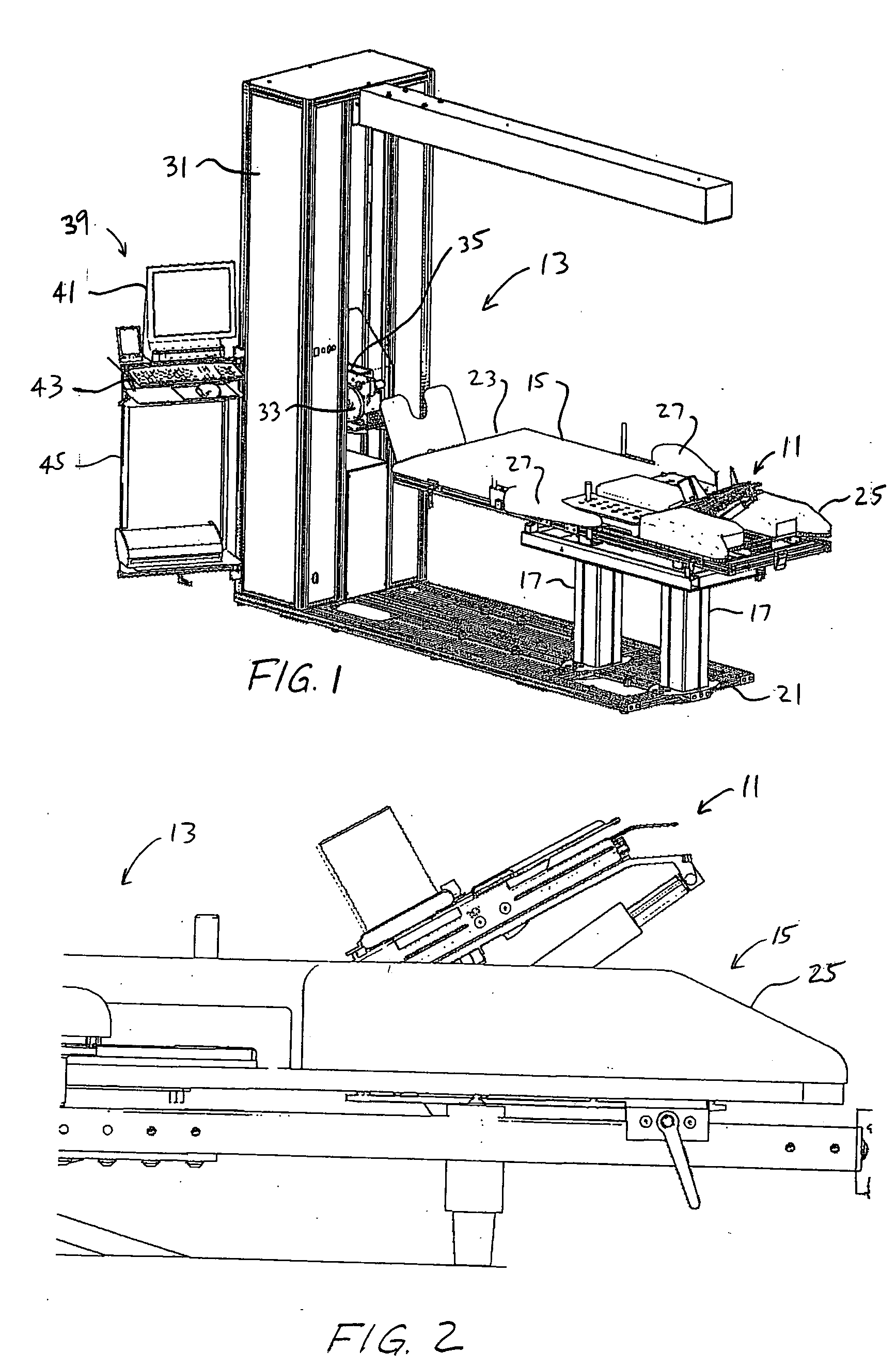
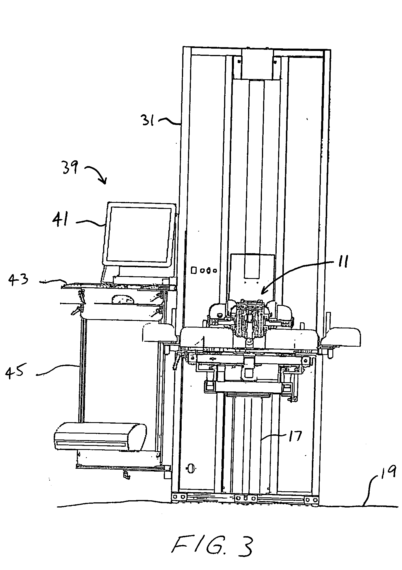
[0028] Referring to FIG. 1-4, a cervical traction device 11 a...


PUM


Abstract

A cervical traction device includes a base, a cervical force application member, and a motor operably attached to the cervical force application member. The motor preferably drives the cervical application member through a direct drive system in order to provide a force to a person's cervical vertebra. The cervical traction device may also include a linear actuator for elevating the person's head to direct the force applied to the cervical vertebra. When integrated on a vertebral distraction machine, the cervical traction device includes its own motor for applying force to the cervical vertebra.

Description

CROSS-REFERENCE TO RELATED APPLICATIONS [0001] This application claims the benefit of and priority to U.S. Provisional Application No. 60 / 486,049, filed Jul. 10, 2003, which is hereby incorporated by reference.BACKGROUND OF THE INVENTION [0002] 1. Field of the Invention [0003] The present application relates to cervical traction devices that are used to distract cervical vertebra for relieving pain and discomfort associated with cervical misalignment and compression. [0004] 2. Description of Related Art [0005] Vertebral traction machines and vertebral decompression machines (collectively referred to herein as “vertebral distraction machines”) have been successfully used to treat vertebral misalignment and compression in people suffering mild to severe back pain. By applying a distractive force to the vertebra, the machines are able to assist in decompressing or realigning the affected vertebra, thereby relieving the associated pain. Although some machines have been developed for hom...

Claims


Application Information

Patent Timeline
IPC IPC(8): A61F5/04A61H1/02
CPCA61F5/04A61H1/0218A61H2203/0493A61H2201/1607A61H1/0222
Inventor BECERRA, CARLOSSMITH, NORMAN A.RANDEL, MARKUSCOPELAND, TONY
Owner NORTH AMERICAN MEDICAL CORPORTAION
Why Eureka
Try Eureka