
Implantable medical devices

a medical device and implantable technology, applied in the direction of prosthesis, catheter, blood vessel, etc., can solve the problems of prostate hyperplasia, difficult or impossible urination, and dangerous conditions,

Inactive Publication Date: 2005-01-13
UNIV OF CONNECTICUT +2
View PDF99 Cites 375 Cited by
  • Summary
  • Abstract
  • Description
  • Claims
  • Application Information

AI Technical Summary

Benefits of technology

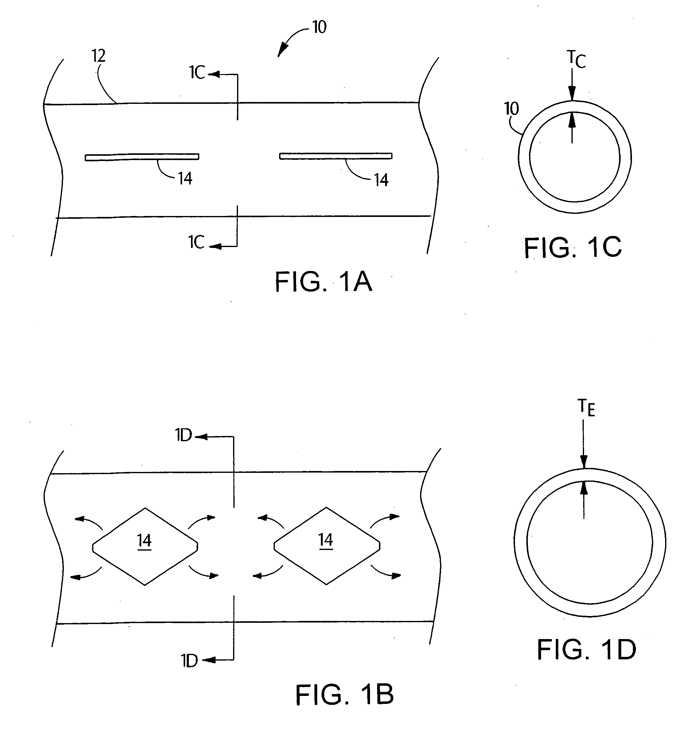
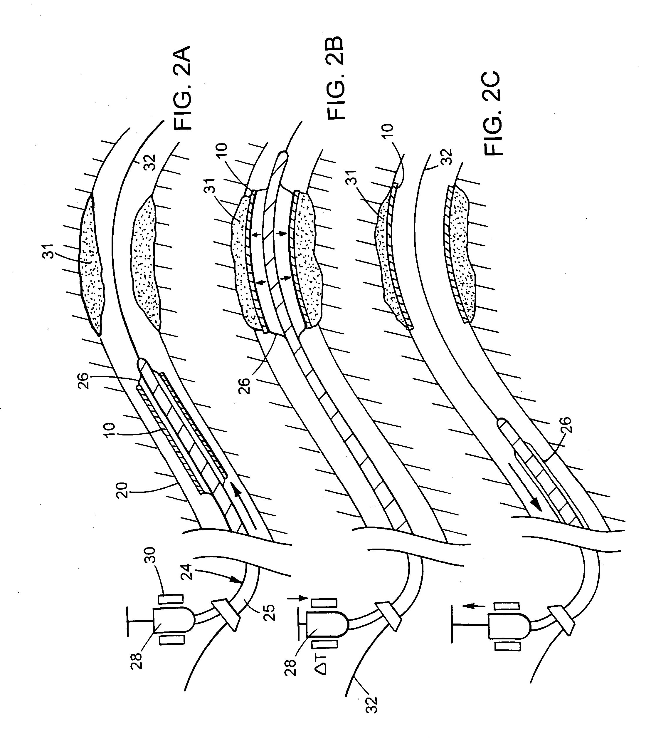
The invention relates to implantable medical devices made of a polymer body, such as stents, that can be expanded within the body by inflating a balloon catheter. The polymer body is made of a crosslinked or crystalline polymer that does not flow significantly during expansion, and the geometry of the device is maintained during use. The polymer body may include apertures and the endoprosthesis can be expanded to a larger diameter without losing its shape. The invention also includes a method for triggering the expansion of the device using a heat applicator. The polymer body may be made of a shape memory polymer that can remember its smaller diameter configuration after expansion. The invention provides a solution for creating implantable medical devices that can be expanded within the body without losing their shape or causing significant stress relaxation or creep.

Problems solved by technology

Benign prostate hyperplasia is uncomfortable because it makes urination difficult or impossible.
The condition is also dangerous because it can lead to infection of the bladder and kidneys.

Method used


Image

  • Implantable medical devices
  • Implantable medical devices
  • Implantable medical devices

Examples


example 1

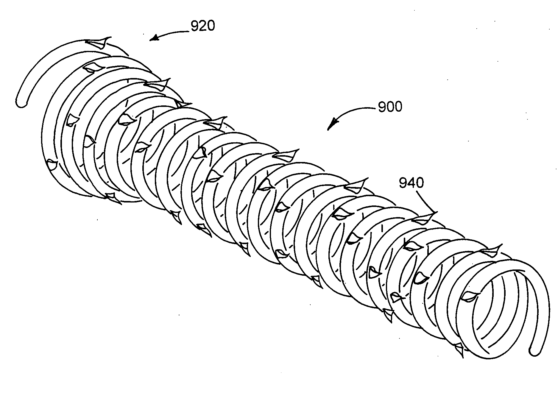
A 56:24:20 mixture of PVAc / PVDF / PMMA is dry bended and loaded into the hopper of an extruder. The PVAc is grade B-100, the PVDF is Solvay SOLEF® 1010 and the PMMA is Atofina PLEXIGLAS® V045. The mixture is melt processed to produce 1.27 mm (0.05 inch) monofilament. The rod is made into a coil by winding it around wrapping fixture 200. The fixture and the rod are immersed into a 50° C. water bath. At this temperature, the rod becomes malleable enough to wind easily around the mandrel and secured in place to prohibit the uncoiling of the helical shape. The mandrel is removed from the fixture with the stent locked in place and placed into an oven at 110° C. for one hour to anneal the stent. This annealing process locks the permanent shape of the coil. The mandrel and coil are cooled to room temperature, and the stent is removed from the mandrel. The stent had on overall length of approximately 73 mm and a flared end portion length of approximately 7 mm. The diameter d1 of the body is ...

example 2

A 70:30 mixture of PVAc / PVDF is dry bended and loaded into the hopper of an extruder. The mixture is melt processed to produce 1.27 mm (0.05 inch) monofilament. The rod is made into a coil by winding it around wrapping fixture 200. The fixture and the rod are immersed into a 50° C. water bath. At this temperature, the rod becomes malleable enough to wind easily around the mandrel and secured in place to prohibit the uncoiling of the helical shape. The mandrel is removed from the fixture with the stent locked in place and placed into an oven at 110° C. for one hour to anneal the stent. This annealing process locks the permanent shape of the coil. The mandrel and coil are cooled to room temperature, and the stent is removed from the mandrel. The stent had on overall length of approximately 73 mm and a flared end portion length of approximately 7 mm. The diameter d1 of the body is approximately 6 mm and the maximum diameter d2 of the flare on the open end is approximately 11 mm. Befor...


PUM

PropertyMeasurementUnit
melt temperatureaaaaaaaaaa
glass transition temperatureaaaaaaaaaa

Abstract

A medical device includes a balloon catheter having an expandable member, e.g., an inflatable balloon, at its distal end and a stent or other endoprosthesis. The stent is, for example, an apertured tubular member formed of a polymer and is assembled about the balloon. The stent has an initial diameter for delivery into the body and can be expanded to a larger diameter by inflating the balloon.

Description

TECHNICAL FIELD This invention relates to implantable medical devices and methods of delivering the same. BACKGROUND The body includes various passageways such as arteries, other blood vessels, and other body lumens. These passageways sometimes become occluded or weakened. For example, the passageways can be occluded by a tumor, restricted by plaque, or weakened by an aneurysm. When this occurs, the passageway can be reopened or reinforced, or even replaced, with a medical endoprosthesis. An endoprosthesis is typically a tubular member that is placed in a lumen in the body. Examples of endoprosthesis include stents and covered stents, sometimes called “stent-grafts”. An endoprosthesis can be delivered inside the body by a catheter that supports the endoprosthesis in a compacted or reduced-size form as the endoprosthesis is transported to a desired site. Upon reaching the site, the endoprosthesis is expanded, for example, so that it can contact the walls of the lumen. Prostate enl...

Claims


Application Information

Patent Timeline
Patent Type & Authority Applications(United States)
IPC IPC(8): A61F2/00A61F2/84A61F2/88A61L29/14A61L31/14C08G18/38C08G18/48C08G18/61C08G18/71C08G61/08C08G65/336C08J3/00C08L65/00C08L71/02
CPCA61F2/88A61F2220/0016A61F2002/8483A61F2250/0037A61L31/14A61M27/008C08G18/3893C08G18/4833C08G18/61C08G18/718C08G61/08C08G65/336C08G2230/00C08J3/005C08L65/00C08L71/02C08L2205/05A61F2/958C08L83/00
Inventor SAHATJIAN, RONALD A.TAN, FRANCISCAMATHER, PATRICKLIU, CHANGDENG
Owner UNIV OF CONNECTICUT
Learn More