Refrigerator-electronics architecture

Inactive Publication Date: 2005-01-20
HAIER US APPLIANCE SOLUTIONS INC
View PDF43 Cites 89 Cited by
  • Summary
  • Abstract
  • Description
  • Claims
  • Application Information

AI Technical Summary

Benefits of technology

In an exemplary embodiment, an electronic control system is provided for a refrigeration system including at least one refrigeration compartment and a quick chill/thaw pan located in the refrigeration compartment. The control system includes a main controller board, a temperature adjustment board, a dispenser board, and a serial communications bus. The main controller board is electrically connected to the temperature adjustment board and the dispenser board through the serial communications bus for controlling the temperature of the refrigeration compartment and the quick chill/thaw pan. The control system transmits commands over the serial communications bus to the dispenser board and the temperature adjustment board. The control system accepts a plurality of inputs including a refrigeration compartment temperature and a quick chill/thaw mode, determines a state of the refrigeration system, transmits commands over the serial communications bus, and executes a plurality of algorithms to control the refrigeration compartment and the quick chill/thaw pan over the serial communications bus.
The control system further includes a human machine interface board operatively coupled to the main controller board for user manipulation to select features of the refrigeration system, such as operation mode of the quick chill/thaw pan, to input user-selected operating setpoints such, as for example, a desired refrigeration compartment temperature, and to display actual temperature conditions and selected features of the refrigerator system.
The control system i

Problems solved by technology

Conventionally, different control systems have been employed to control different refrigerator platforms, which is undesirable from a manufacturing and service perspective.
In addition, typical refrigerators require extended periods of time to cool food and beverages placed therein.
If not closely monitored, the items will freeze and possibly break the packaging enclosing the item and creating a mess in the freezer compartment.
These compartments, however, undesirably reduce refrigerator compartment space, are difficult to clean and service, and h

Method used


Image

  • Refrigerator-electronics architecture
  • Refrigerator-electronics architecture
  • Refrigerator-electronics architecture

Examples


Embodiment Construction

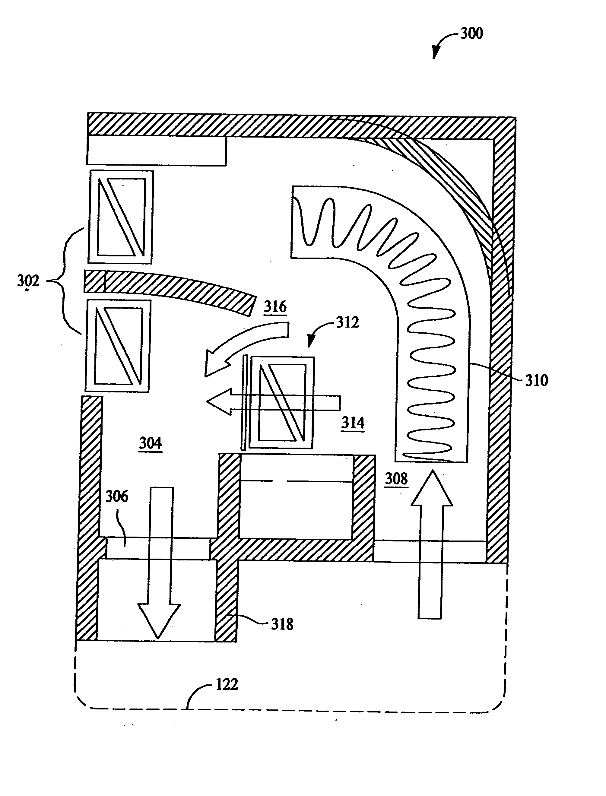
FIG. 1 illustrates a side-by-side refrigerator 100 in which the present invention may be practiced. It is recognized, however, that the benefits of the present invention apply to other types of refrigerators. Consequently, the description set forth herein is for illustrative purposes only and is not intended to limit the invention in any aspect.

Refrigerator 100 includes a fresh food storage compartment 102 and freezer storage compartment 104. Freezer compartment 104 and fresh food compartment 102 are arranged side-by-side. A side-by-side refrigerator such as refrigerator 100 is commercially available from General Electric Company, Appliance Park, Louisville, Ky. 40225.

Refrigerator 100 includes an outer case 106 and inner liners 108 and 110. A space between case 106 and liners 108 and 110, and between liners 108 and 110, is filled with foamed-in-place insulation. Outer case 106 normally is formed by folding a sheet of a suitable material, such as pre-painted steel, into an inverte...


PUM


Abstract

A control system for a refrigeration system having a refrigeration compartment and a quick chill/thaw pan. A main controller board, electrically connected to a temperature adjustment board and a dispenser board through the serial communications bus, controls the temperature of the refrigeration compartment and the quick chill/thaw pan. The control system accepts a plurality of inputs to determine a refrigeration mode and to execute a plurality of software algorithms to control the refrigeration compartment as both a chill pan to rapidly chill food and beverage items without freezing and a thaw pan to timely thaw frozen items at controlled temperature levels.

Description

BACKGROUND OF THE INVENTION This invention relates generally to refrigeration devices, and more particularly, to control systems for refrigerators. Current appliance revitalization efforts require electronic subsystems to operate different appliance platforms. For example, known household refrigerators include side-by-side single and double fresh food and freezer compartments, top mount, and bottom mount type refrigerators. A different control system is used in each refrigerator type. For example, a control system for a side-by-side refrigerator-controls the freezer temperature by controlling operation of a mullion damper. Such refrigerators may also include a fresh food fan and a variable or multi-speed fan-speed evaporator fan. Top mount refrigerators and bottom mount refrigerators are available with and without a mullion damper, the absence or presence of which affects the refrigerator controls. Therefore, control of the freezer temperature in top and bottom mount type refriger...

Claims


Application Information

Patent Timeline
IPC IPC(8): F25D11/02F25D29/00F25D31/00
CPCF25D2700/02F25D2700/14F25B2600/23F25D11/02F25D2400/36F25D31/005F25D2400/06F25D2400/28F25D29/00F25B49/022F25B49/027F25D23/12F25D29/005F25D29/008F25D2400/02F25D2400/34F25D2600/06
Inventor HOLMES, JOHN S.QUEEN, JERRY J. IIHERZOG, ROLLIE R.MATHEWS, MARK ROBERTBULTMAN, ROBERT M.HOLDER, TIMDAUM, WOLFGANG
Owner HAIER US APPLIANCE SOLUTIONS INC
Why Eureka
Try Eureka