Method and apparatus for vibration sensing and analysis

a vibration sensing and analysis method technology, applied in the direction of material analysis using wave/particle radiation, instruments, and static/dynamic balance measurement, etc., can solve the problems of unfavorable dynamic range, unfavorable dynamic range, and improper gear meshing of excitation sources

Inactive Publication Date: 2005-01-20
PCB PIEZOTRONICS IMI SENSORS +1
View PDF17 Cites 162 Cited by
  • Summary
  • Abstract
  • Description
  • Claims
  • Application Information

AI Technical Summary

Benefits of technology

[0027] This and other objects, features and advantages of the invention will become readily apparent to one having...

Problems solved by technology

The excitation sources can be unbalance, misalignment, improper gear meshing, a loose machine relative to its housing, defective bearings, etc.
For an instrument operating in the linear domain, ...

Method used


Image

  • Method and apparatus for vibration sensing and analysis
  • Method and apparatus for vibration sensing and analysis
  • Method and apparatus for vibration sensing and analysis

Examples


Embodiment Construction

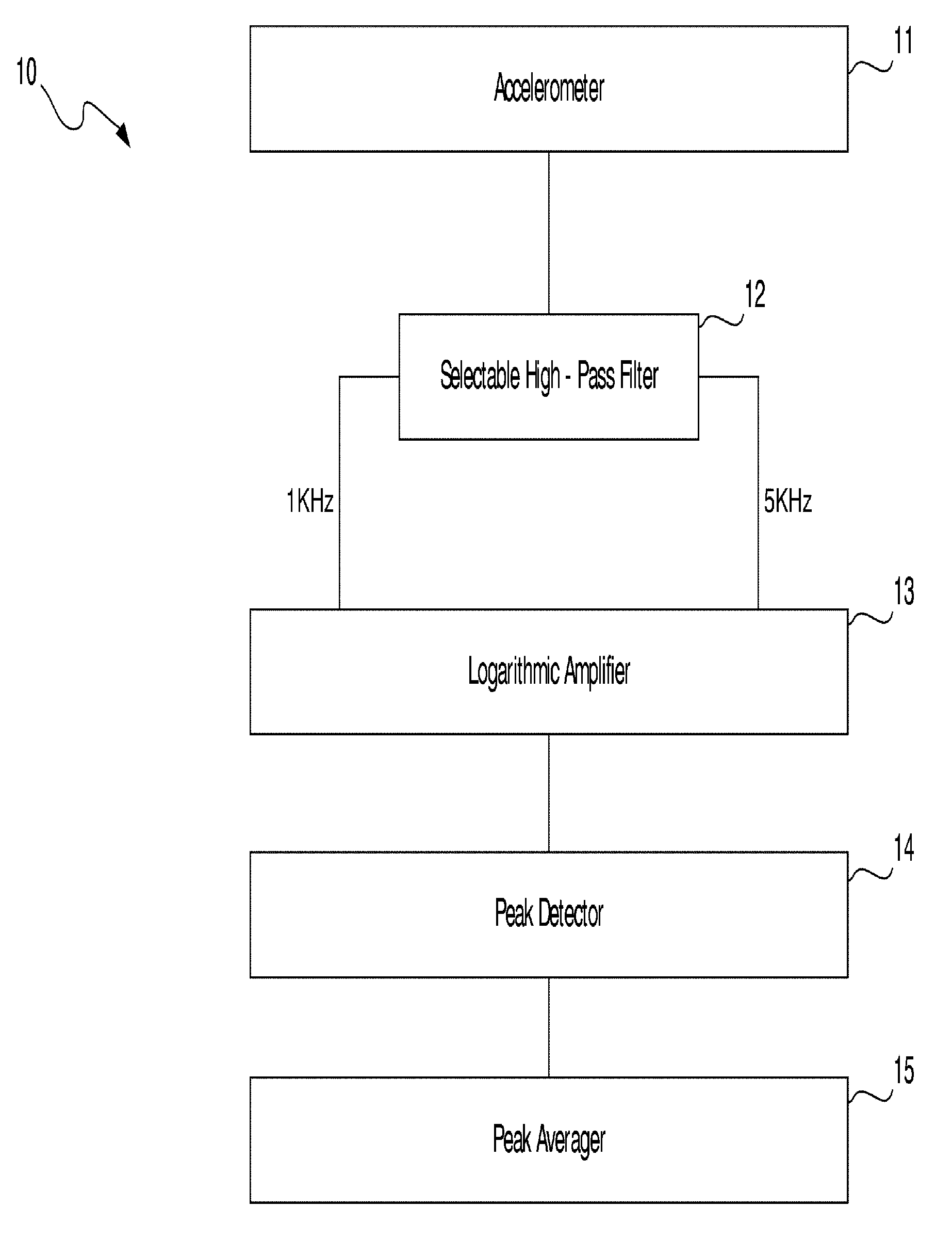
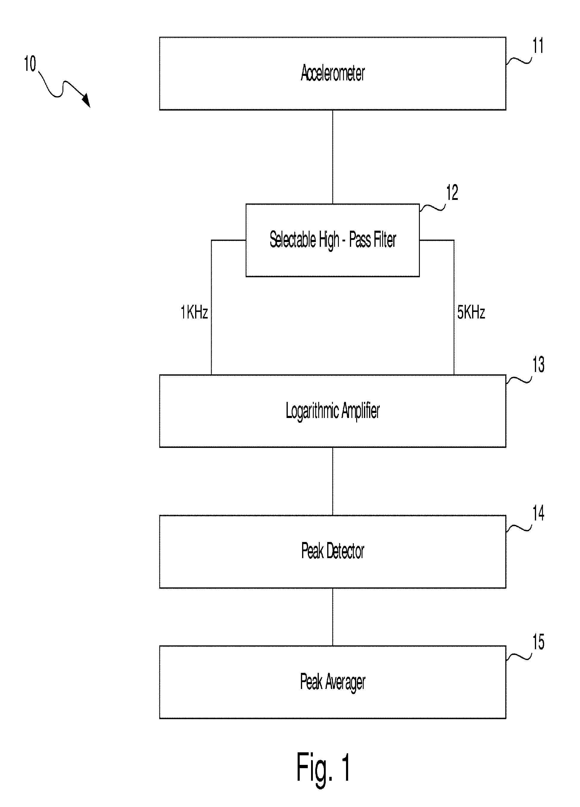
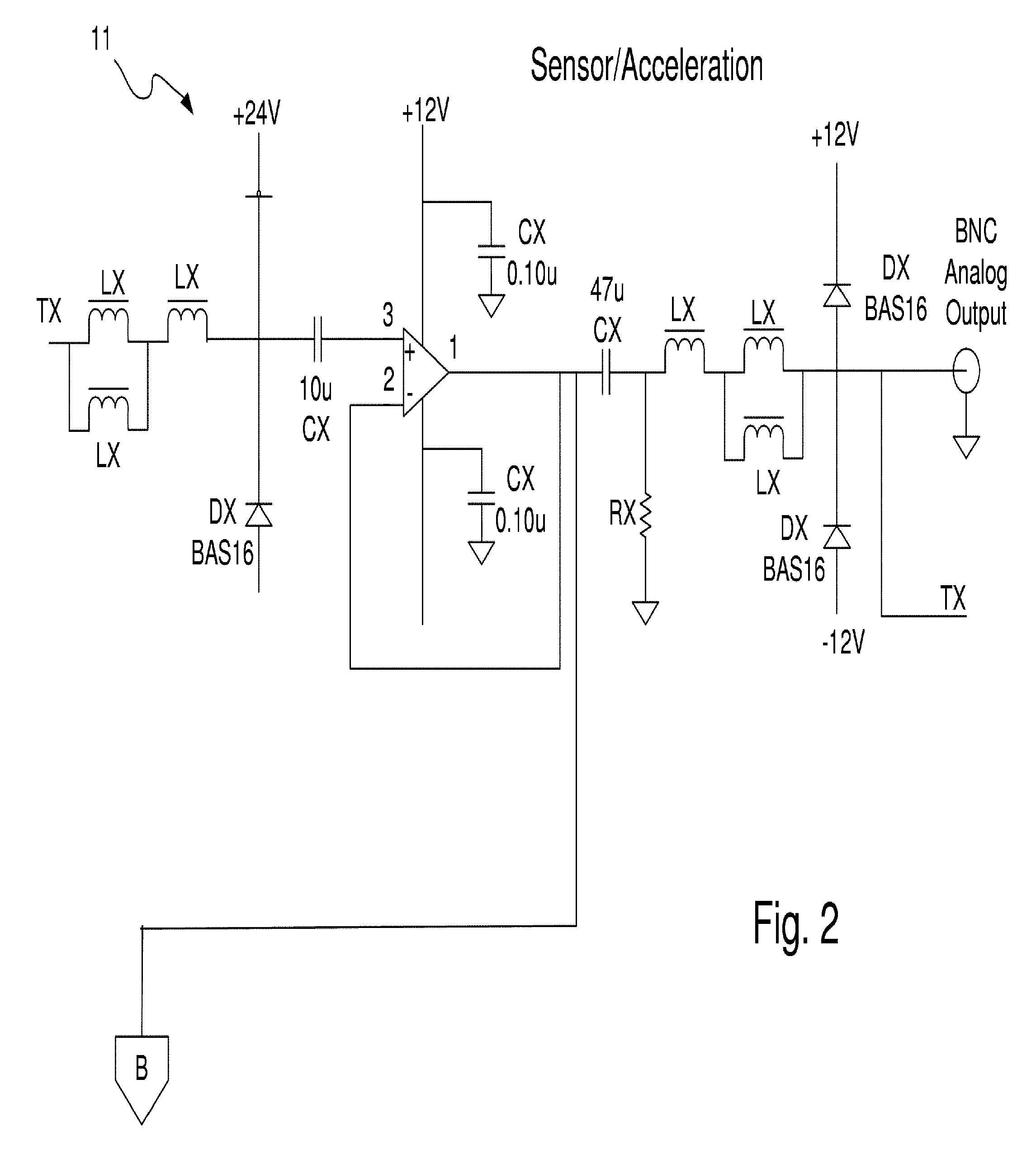
[0036] At the outset it should be appreciated that identical reference numbers on different drawing views represent identical circuit components or elements. It should also be appreciated that the drawing figures illustrate an actual circuit diagram, with all circuit elements and values thereof, sufficient to enable one having ordinary skill in the art to make and use the invention. Finally, it should be appreciated that, while the disclosed circuit represents the best mode of practicing the apparatus of the invention, it is by no means the only mode. The method of the invention may be implemented by other circuits with other components. Not all of the circuit elements in the disclosed circuit are necessary. For example, in some applications, a strain gauge may be preferable to an accelerometer. Also, different target frequencies for the high pass filter (or, alternatively, a band pass filter) of the circuit may be used.

[0037] Generally, in a preferred embodiment the present invent...


PUM


Abstract

A method and apparatus for sensing and measuring stress waves. The method comprises the steps of: a.) sensing motion, where the motion comprises a stress wave component and a vibration component; b.) separating the stress wave component from the vibration component with a high pass filter to create a signal proportional to the stress wave; c.) amplifying the signal to create an amplified signal; d.) processing the amplified signal with a sample and hold peak detector over a predetermined interval of time to determine peaks of the amplified signal over said predetermined period of time; e.) creating an output signal proportional to the determined peaks of the amplified signal; and, f.) repeating steps d.) and e.). The invention also includes an apparatus for implementing the method of the invention.

Description

FIELD OF THE INVENTION [0001] The present invention relates generally to an improved vibration sensing and analysis method and apparatus. More specifically, the invention relates to a method and apparatus for measuring macroscopic and microscopic vibration of machines, which includes the use of a selectable high pass filter, logarithmic amplifier, sample and hold peak detector, and peak averager. BACKGROUND OF THE INVENTION [0002] Rotating members generally are supported by a stationary body through bearings where, for example, the outer race of the bearing is permanently affixed to an outer housing and the inner race is permanently affixed to a rotating shaft. Rollers are placed between the inner and outer races and permit, with proper lubrication, the rotating element to turn freely with little restraint. If the rolling element experiences forces which cause it to operate off rotational center, forces are transmitted to the stationary body through the bearings inducing slight osci...

Claims


Application Information

Patent Timeline
IPC IPC(8): G01H1/14G01H1/16
CPCG01H1/16G01H1/14
Inventor ROBINSON, JAMES C.FULCINITI, NICOLASILLIG, MITCHELL J.ASHTON, WILLIAM J.
Owner PCB PIEZOTRONICS IMI SENSORS
Why Eureka
Try Eureka