Flexible liner air gap pipe

Inactive Publication Date: 2005-01-20
AMERICAN BOA
View PDF99 Cites 24 Cited by
  • Summary
  • Abstract
  • Description
  • Claims
  • Application Information

AI Technical Summary

Benefits of technology

[0010] Use of the combined rigid wall and flexible wall of selected profile facilitates tube bending, maintains concentricity, reduces pipe noise and vibration and allows for thermal expansion where heat is a factor. Thermal loss of t

Problems solved by technology

Such bending techniques are typically expensive.
And if the bending process is not carefully planned and monitored, the two co

Method used


Image

  • Flexible liner air gap pipe
  • Flexible liner air gap pipe
  • Flexible liner air gap pipe

Examples


Example

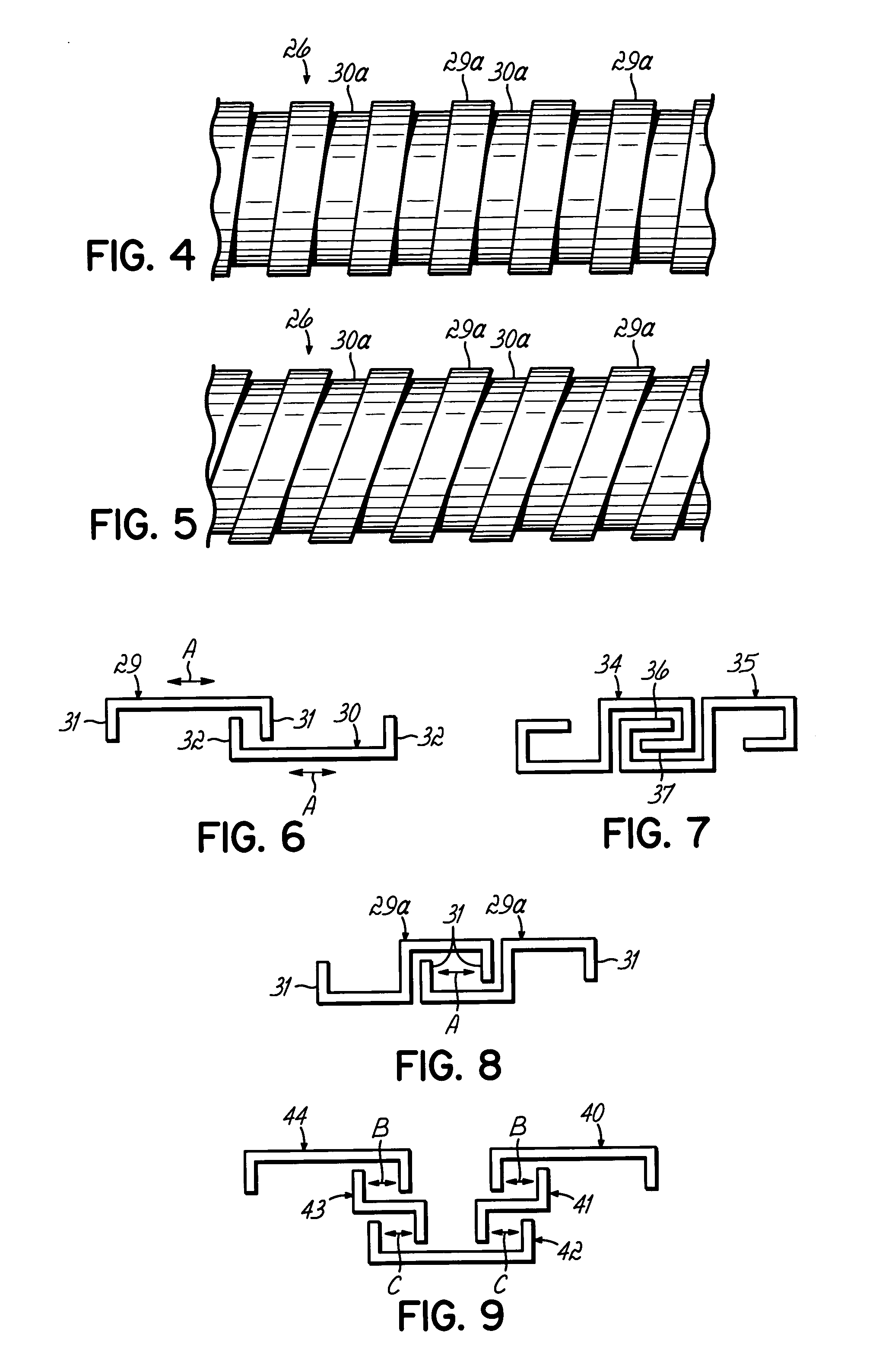
[0049] Turning now to the drawings, it will be appreciated that the Figures are diagrammatic in nature. For example, FIGS. 6-11 simply illustrate only portions of cross-sections of the elongated profiles defining a flexible wall of the invention. And FIG. 12-30 show the flexible wall only diagrammatically, with the described and other alternative profiles possible.

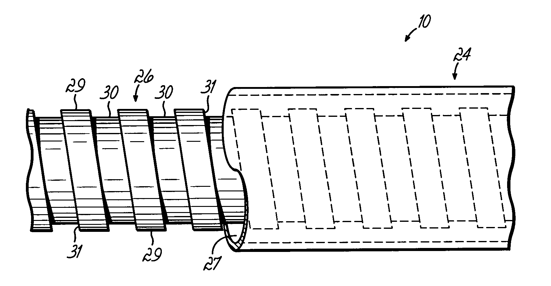
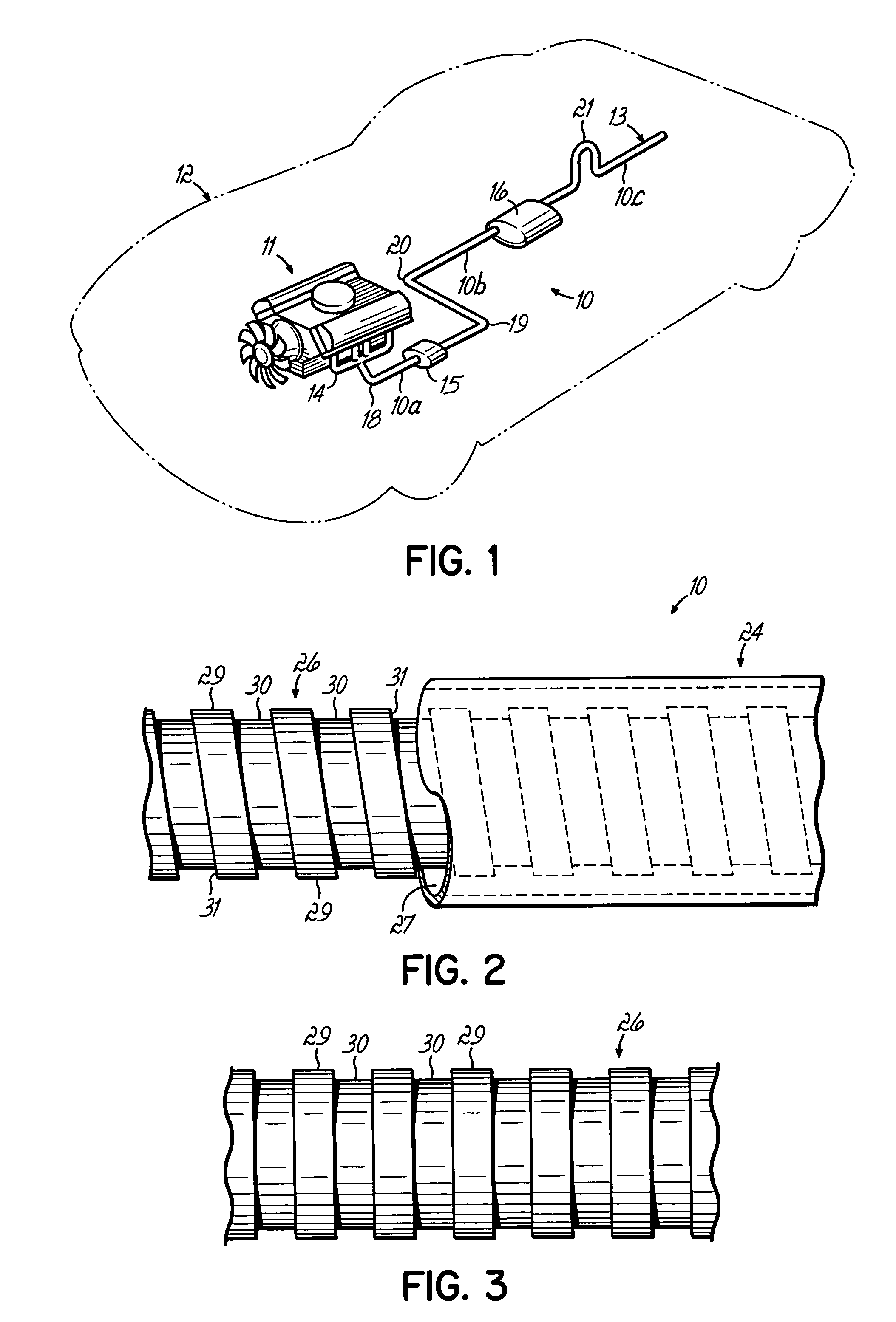
[0050] There is illustrated in FIG. 1 one application of a flexible liner air gap pipe 10 according to the invention as applied to convey exhaust gas from an internal combustion engine 11 in a vehicle 12 to a tailpipe 13. One section 10a of pipe 10 runs from an exhaust manifold14 to a converter 15. Another secton 10b of pipe 10 runs from converter 15 to muffler 16. Another section 10c of pipe 10 runs from muffler 16 to tailpipe 13. Each section 10a-10c is preferably of similar construction, although only a single such section of the exhaust system, according to the invention, with other forms of conduit serving to convey ...


PUM


Abstract

A multiple wall air gap pipe includes a rigid tube wall and at least one flexible tube wall defined by two or more overlapping profiles in wound, interlocking configurations. The multiple wall air gap pipe can be bent on conventional single wall pipe bending apparatus, inexpensively, while retaining the benefits of multiple wall air gap pipes.

Description

[0001] This invention relates to conduits for transferring gas, liquid and solids and in particular in one application to exhaust gas conduits for internal combustion engines and for other applications where bending of air gap or multiple wall conduit is required. BACKGROUND OF THE INVENTION [0002] In the past, it has been common to convey exhaust gas from an internal combustion engine of a vehicle, for example, to other components in the exhaust system and finally to a discharge end or tailpipe. Typically, rigid tubes of suitable material, gauge and diameter are used. For example, steel tubes or conduits of about 0.02 inches gauge to about 0.2 inches gauge and anywhere from one inch or less to twelve inches or more in diameter are used, though other parameters of exhaust pipes may be found. [0003] In varied applications, it is desirable and, in many cases necessary, to orient the tubes or conduit in a tortious, curved or other path which is not straight. Thus, the axis of the tube ...

Claims


Application Information

Patent Timeline
IPC IPC(8): F16L11/16
CPCF16L11/16F01N13/1816
Inventor CHAHINE, PAULMURRAY, PETER H.EARL, JOHN G.
Owner AMERICAN BOA
Why Eureka
Try Eureka