Devices for regulating pressure and flow pulses

a technology of flow pulses and regulating devices, which is applied in the direction of machines/engines, positive displacement liquid engines, exhaust treatment, etc., can solve the problems of adversely affecting increasing the pressure differential between and enhancing the internal and external pressures of the regulating device. , to achieve the effect of enhancing the operation efficiency of the source, reducing the noise generated, and reducing the nois

Active Publication Date: 2005-01-20
DADD PAUL M
View PDF19 Cites 35 Cited by
  • Summary
  • Abstract
  • Description
  • Claims
  • Application Information

AI Technical Summary

Benefits of technology

[0006] The present invention regulates the pressure pulses and flow pulses emitted in the exhausts of apparatus and equipment of the types referred to above. Specifically, the pressure and flow pulses are directed to a reflecting member where at least a portion of each of the pressure pulses is reflected. This feature and the arrangement of other components of the device of the invention serve to attenuate the noise generated by the pressure and flow pulses. Also, because the pressure pulses are reflected as expansion waves back to the location where the pressure and flow pulses are emitted, the expansion waves create a reduced pressure zone at that location. As a result, the flow pulses can be more easily emitted from the source, thereby enhancing the operational efficiency of the source. This procedure is referred to herein as “tuning”. The flow pulses are made up of the exhaust products, such as the products of combustion from an internal combustion engine, and generate an exhaust flow which, if not efficiently conveyed away from the source, will create a back pressure that will resist the emission of flow pulses from the source and adversely affect the operational efficiency of the source. The failure to efficiently convey away from the source the exhaust flow results in an increased pressure differential between the internal and external pressures of the regulating device. This pressure differential is referred to herein as “flow loss”.

Problems solved by technology

The flow pulses are made up of the exhaust products, such as the products of combustion from an internal combustion engine, and generate an exhaust flow which, if not efficiently conveyed away from the source, will create a back pressure that will resist the emission of flow pulses from the source and adversely affect the operational efficiency of the source.
The failure to efficiently convey away from the source the exhaust flow results in an increased pressure differential between the internal and external pressures of the regulating device.

Method used


Image

  • Devices for regulating pressure and flow pulses
  • Devices for regulating pressure and flow pulses
  • Devices for regulating pressure and flow pulses

Examples


first embodiment

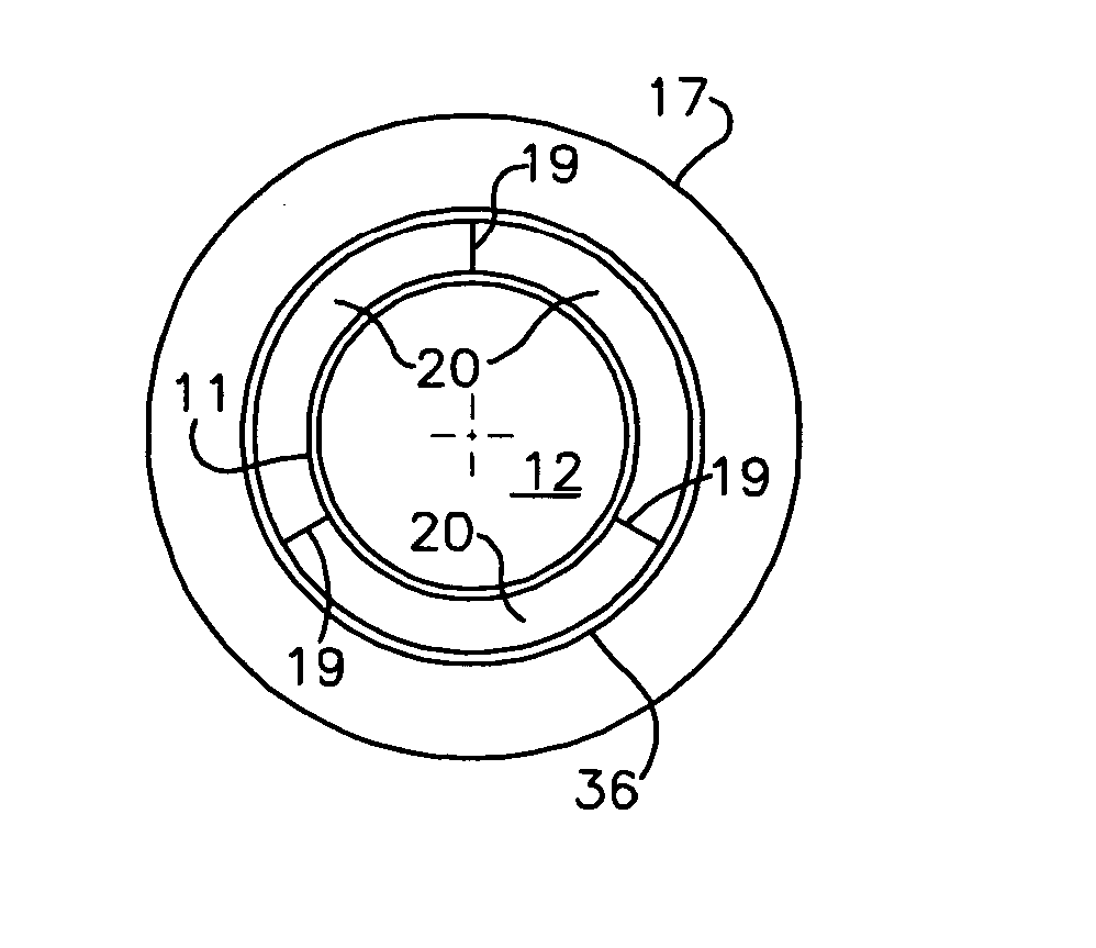
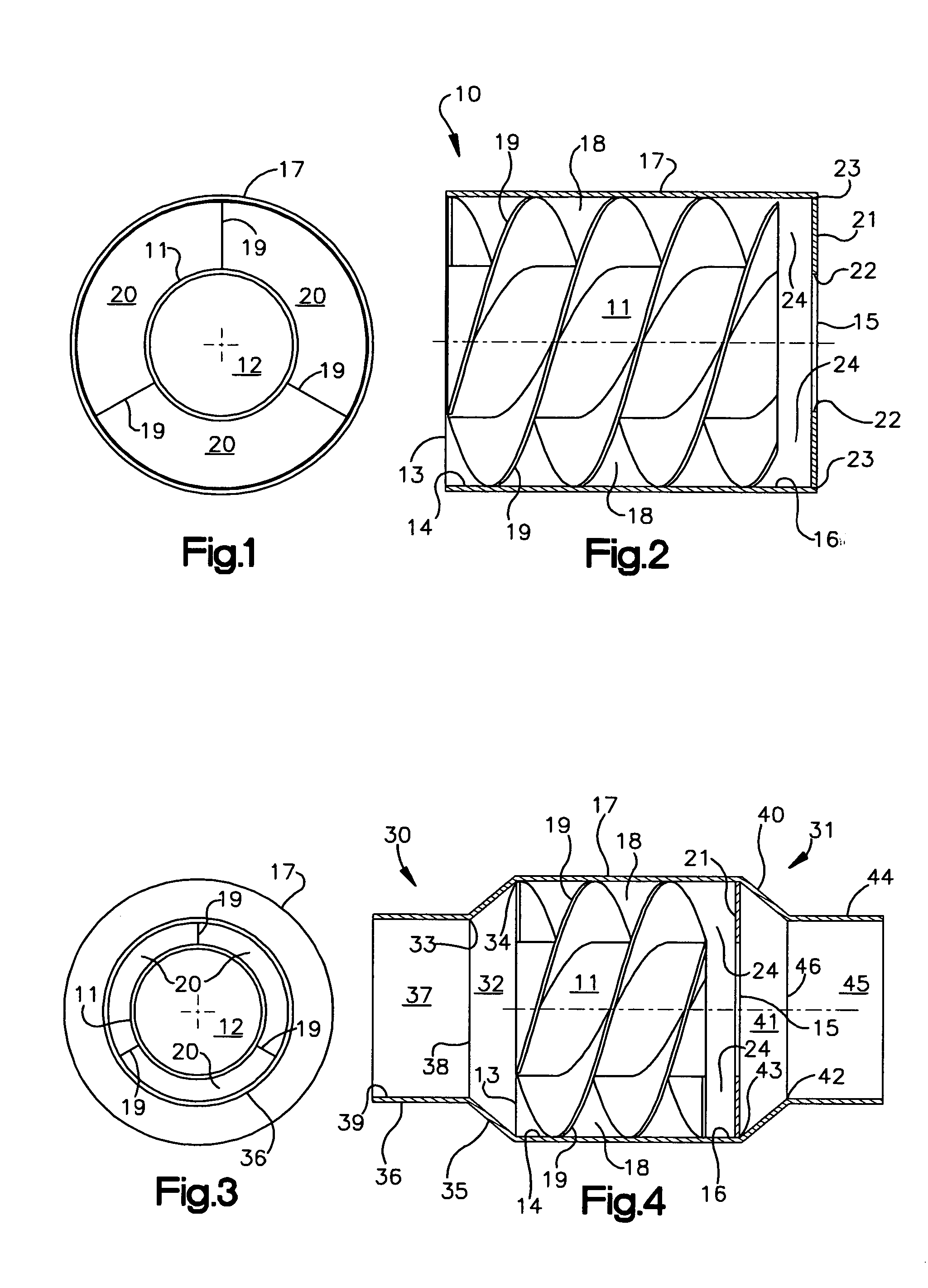
[0024] Means are located in the annular space 18 between the first and second enclosures 11 and 17, respectively, for establishing in the annular space at least one second passageway in the form of a helical passageway that extends between the opening 13 in the entry end14 of the device and a location short of the opening 15 in the exit end 16 of the device. In the invention illustrated in FIGS. 1 and 2, the means for establishing at least one second passageway comprises three vanes 19, each of which is helically wound around the exterior of the cylindrical shell 11 along the entire length of the shell. Adjacent ones of the vanes 19 are spaced apart an equal distance so as to form three substantially identical helical passageways 20 in the annular space 18, each helical passageway having a length greater than the first passageway. It will be understood by those skilled in the art based on the description herein that less than or more than three vanes can be used and the passageways ...

second embodiment

[0033] In the invention shown in FIGS. 3 and 4, the device 10, as described above, includes, in addition, an inlet end, indicated generally at 30, and an outlet end, indicated generally at 31. The inlet end 30 includes a third enclosure 35 that defines a third passageway 32 that has the configuration of a truncated cone with a truncated end 33 and a base end 34. The cross-sectional area of the base end 34 of the third passageway 32 is approximately equal to the cross-sectional area of the opening 13 in the entry end 14. The third enclosure 35 at the base end 34 of the third passageway 32 is connected to the second enclosure 17 so that the base end 34 of the third passageway 32 adjoins the opening 13 in the entry end 14 in a face-to-face relationship. The inlet end 30 also includes a fourth enclosure 36 that defines a fourth passageway 37 having the configuration of a cylinder. One end 38 of the fourth enclosure 36 is connected to the third enclosure 35 at the truncated end 33 of the...

fourth embodiment

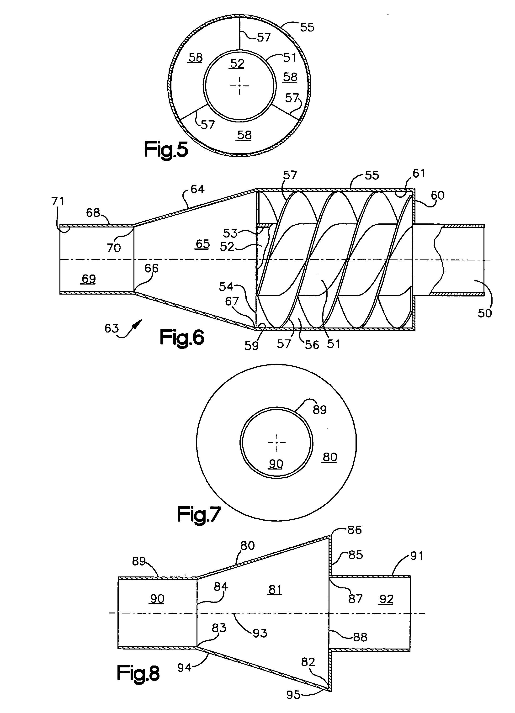
[0043] the invention, as illustrated in FIGS. 7 and 8, also includes a second enclosure 89 that defines a second passageway 90 that has the configuration of a cylinder with a cross-sectional area that is preferably equal to the cross-sectional area of the opening 84 in the entry end 94 of the device. The second enclosure 89 is connected at one end to the first enclosure at the truncated end 83 of the first passageway 81 so that the second passageway 90 provides for fluid communication between the engine and the opening 84 in the entry end 94 of the device. A third enclosure 91 defines a third passageway 92 that has the configuration of a cylinder with a cross-sectional area that is preferably equal to the cross-sectional area of the opening 88 in the exit end 95 of the device. The third enclosure 91 is connected to the inner circumference 87 of the annulus 85 so that the third passageway 92 provides for fluid communication from the opening 88 in the exit end 95 of the device away fr...


PUM


Abstract

Devices are provided for regulating the pressure pulses and flow pulses that are emitted in the exhausts of apparatus and equipment such as internal combustion engines, compressors and poppet valves. The pressure pulses are reflected from a reflecting member to their source as expansion waves that create a reduced pressure zone that allows subsequently emitted flow pulses to be more easily emitted, thereby enhancing the operational efficiency of the apparatus and equipment. Flow pulses that contain exhaust products such as the products of combustion from an internal combustion engine are regulated so that the exhaust flow they generate is not unduly restricted within the device and an undesirable back pressure that resists the emission of flow pulses from their source created. In regulating the pressure and flow pulses, the devices attenuate the noise generated by the pressure and flow pulses.

Description

[0001] The benefit of provisional application Ser. No. 60 / 487,404, filed on Jul. 14, 2003, and incorporated herein by reference is claimed for this application.[0002] The present invention relates to devices for regulating pressure pulses and flow pulses that are emitted in the exhausts of various apparatus and equipment. BACKGROUND OF THE INVENTION [0003] Apparatus and equipment such as, for example, internal combustion engines, compressors and poppet valves emit pressure pulses and flow pulses in their exhausts. In certain of the apparatus and equipment, such as the internal combustion engines, products of combustion comprise the flow pulses. The pressure and flow pulses are sources of noise, and the flow pulses can create a back pressure that adversely affects the operational efficiency of the apparatus and equipment. [0004] The known exhaust systems that are employed with the aforementioned sources of pressure and flow pulses for the purpose of receiving and conveying away from ...

Claims


Application Information

Patent Timeline
Patent Type & Authority Applications(United States)
IPC IPC(8): F01N1/06F01N1/12
CPCF01N1/06F01N2260/06F01N1/12
Inventor DADD, PAUL M.
Owner DADD PAUL M
Why Eureka
Try Eureka