Charged particle detector and detecting apparatus utilizing the same

a technology of detecting apparatus and detector, which is applied in the direction of material analysis using wave/particle radiation, instruments, x/gamma/cosmic radiation measurement, etc., can solve the problems of large size of the detector and difficulty in implementing such a multi-channel configuration

Inactive Publication Date: 2005-01-20
HITACHI LTD
View PDF8 Cites 25 Cited by
  • Summary
  • Abstract
  • Description
  • Claims
  • Application Information

AI Technical Summary

Benefits of technology

[0008] To achieve the object in accordance with the present invention, there is provided a dangerous substance detecting apparatus including a metallic frame having one or more holes formed therein, a light transmitting member fixed in each of the holes of the metallic frame, an inorganic scintillation element fixed on a surface of the light transmitting member, the surface being on a first side of the member; and a photodetector disposed on a surface of the light transmitting member, the surface being on a second side opposing the first side of the member. Fluorescence generated by charged particles having entered the inorganic scintillation element is sent via the light transmitting member to the photodetector and is detected by the photodetector.
[0009] In accordance with the present invention, there is provided a detecting apparatus, including a charged particle detector including a metallic frame having one or more holes formed therein, a light transmitting member fixed in each of the holes of the metallic frame, an inorganic scintillation element fixed on a surface of the light transmitting member, the surface being on a first side of the member; and a photodetector disposed on a surface of the light transmitting member, the surface being on a second side opposing the first side of the member; a neutron generator for generating charged particles and neutrons, and a gamma ray detector for detecting gamma rays emitted when the neutrons are radiated onto an inspection object. According to a result of detection by the charged particle detector and a result of detection by the gamma ray detector, elements of the inspection object are identified and thereby detecting an explosive.

Problems solved by technology

However, the conventional vacuum barrier is attended with a problem that the detector is large in its size.
However, when the vacuum barrier has a large size, it is difficult to implement such a multichannel configuration.

Method used


Image

  • Charged particle detector and detecting apparatus utilizing the same
  • Charged particle detector and detecting apparatus utilizing the same
  • Charged particle detector and detecting apparatus utilizing the same

Examples


Embodiment Construction

[0024] Referring now to the drawings, description will be given of an embodiment in accordance with the present invention.

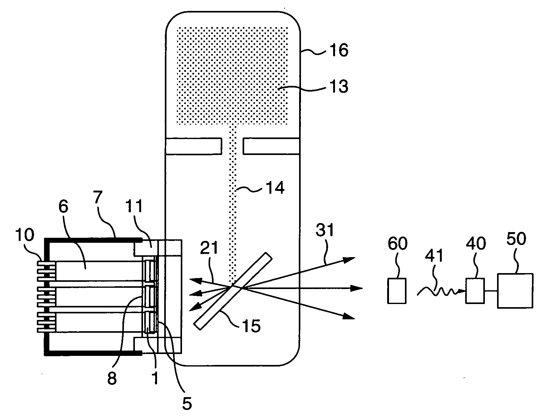
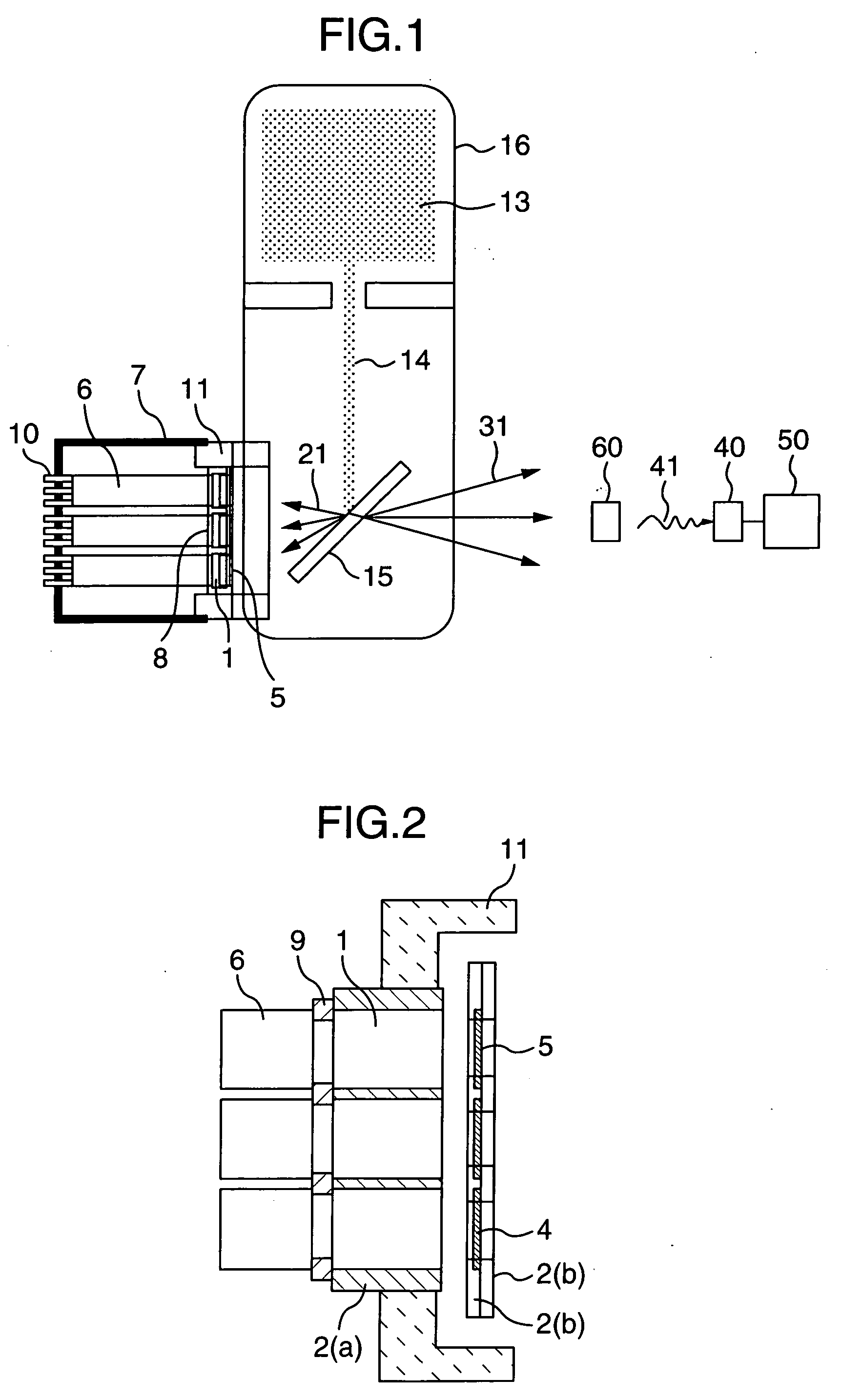
[0025]FIG. 1 shows an embodiment a charged particle detector used with a neutron generator. A flange attaching metallic member or frame 11 is beforehand arranged on a side surface of a neutron generating tube 16. The metallic frame 11 is fixed onto the side surface of the tube 16 by welding or by use of bolts. The tube 16 contains plasma of deuterium 13 and a hydrogen occluding alloy 15. An ion beam of deuterium 15 drawn from the plasma 13 collides with the alloy 15 having occluded tritium. As a result of fusion reaction between deuterium and tritium, alpha rays 21 and neutrons 31 are generated. Since the alpha rays 21 and the neutrons 31 respectively travel in almost opposite flight directions, namely, in the respective directions with an angular difference of about 180° therebetween. Therefore, by identifying creation positions and detection positions of the a...


PUM

PropertyMeasurementUnit
atmospheric pressureaaaaaaaaaa
time resolutionaaaaaaaaaa
softening pointaaaaaaaaaa

Abstract

In a charged particle detector, the vacuum barrier can be reduced in size and a multichannel configuration is possible. A charged particle detector includes a metallic frame having one or more holes formed therein, a light transmitting member fixed in each of the holes of the metallic frame, an inorganic scintillation element fixed on a surface of the light transmitting member, the surface being on a first side of the member; and a photodetector disposed on a surface of the light transmitting member, the surface being on a second side opposing the first side of the member. Charged particles having passed through the inorganic scintillation element are sent via the light transmitting member to the photodetector and are detected by the photodetector.

Description

INCORPORATION BY REFERENCE [0001] The present application claims priority from Japanese application JP 2003-164950 filed on Jun. 10, 2003, the content of which is hereby incorporated by reference into this application. BACKGROUND OF THE INVENTION [0002] The present invention relates to a charged particle detector to detect charged particles and a detecting apparatus including the detector. [0003] The charged particle detectors includes a gas detector, a semiconductor detector, an organic scintillation detector, and an inorganic scintillation detector. [0004] The inorganic scintillation detector includes, as described in, for example, JP-A-2001-183464, a scintillator which is a substance to emit fluorescence when charged particles enter therein and a device to convert the fluorescence into an electric signal. [0005] In a recent detecting apparatus to detect explosives and prohibition drugs using, for example, neutrons generated by a fusion reaction between deuterium and tritium, it i...

Claims


Application Information

Patent Timeline
Patent Type & Authority Applications(United States)
IPC IPC(8): G01N23/00G01T1/20G01T3/06
CPCG01T3/06G01T1/2018
Inventor TADOKORO, TAKAHIROTAKEUCHI, KAZUHIROKAWAKUBO, YUKIOAOKI, MANABUMATSUMOTO, MASAKI
Owner HITACHI LTD
Why Eureka
Try Eureka