
Apparatus for and method of removing a pulley

a pulley and apparatus technology, applied in the field of hand held tools, can solve the problems of less work space for mechanics, less room or space between the engine and the radiator, and the handle of a conventional pipe wrench is not long enough to find clearan

Inactive Publication Date: 2005-01-20
SMITH GALE L +1
View PDF7 Cites 8 Cited by
  • Summary
  • Abstract
  • Description
  • Claims
  • Application Information

AI Technical Summary

Benefits of technology

[0005] Accordingly, it is an object of the present invention to provide a hand held tool to prevent a pulley from rotating around an axis of rotation. A handle portion is provided on the tool to be held by a user of the tool. An engaging portion of the tool is adapted to grip a portion of the pulley and prevent the pulley from rotating around the axis when said handle portion is held by the user.
[0006] Further, it is an object of the present invention to provide a tool used in removing a fan clutch on an automobile engine. The tool has a handle portion for being held by a user of the tool and an engaging portion adapted to grip a rim of the pulley. The handle portion has an elongated rod with a user gripping portion disposed at one end and a connecting portion at another end. The engaging portion prevents the pulley from rotating around its rotating axis has a U-shaped body with a base connected to the connecting portion of said handle portion and two arms extending radially from an axis formed by the elongated rod of said handle portion. The arms are displaced from one another by an amount sufficient to receive the rim of the pulley and have a sufficient size to form a friction surface to inhibit rotation of the pulley around its rotating axis when the arms engage the rim of the pulley.

Problems solved by technology

Thus, there is very little room or space between the engine and the radiator in which a mechanic has available to work in removing this pulley.
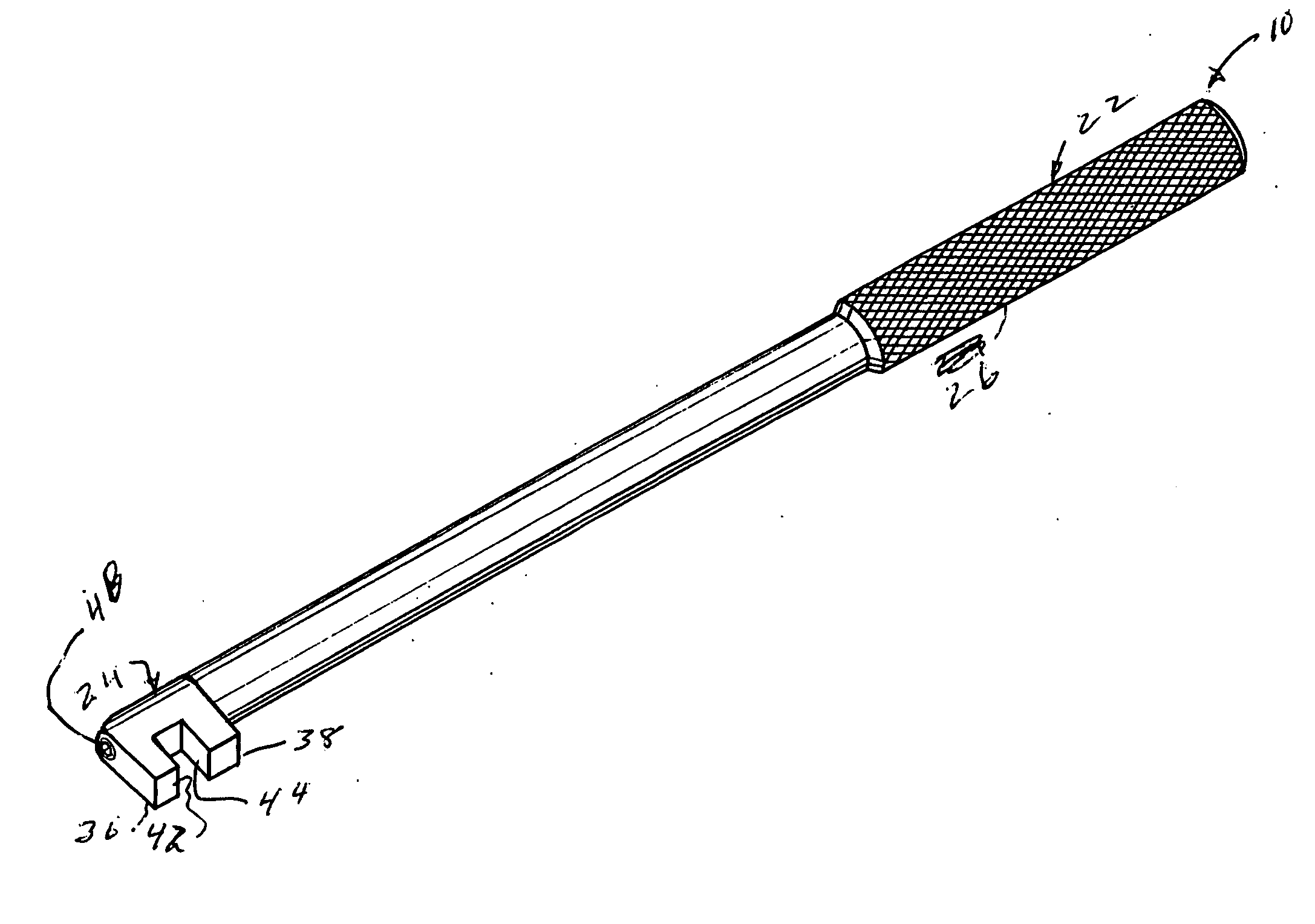
Some tools have been made to prevent pulley from rotating by engaging bolts holding the pulley to the water pump, but these tools leave the mechanic less room to work and will only work on pulleys that have such bolts.
However, the handle on a conventional pipe wrench is not sufficiently long to find clearance among the several parts on the front of the engine.

Method used


Image

  • Apparatus for and method of removing a pulley
  • Apparatus for and method of removing a pulley
  • Apparatus for and method of removing a pulley

Examples


Embodiment Construction

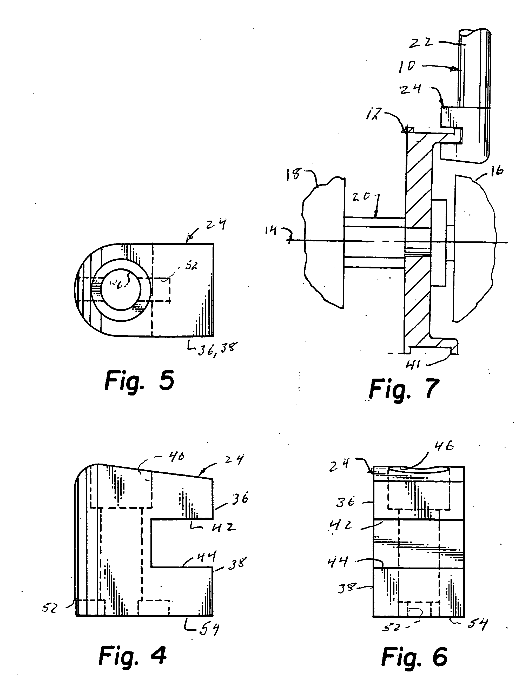
[0016] Turning now to FIGS. 1 and 7, there is shown a hand held tool 10 used to prevent a pulley 12 from rotating its axis of rotation 14. Pulley 12 is used in a motor vehicle to drive a water pump 16 and a fan via a fan clutch 18 that is secured to pulley 12 by a nut 20 in a conventional manner.

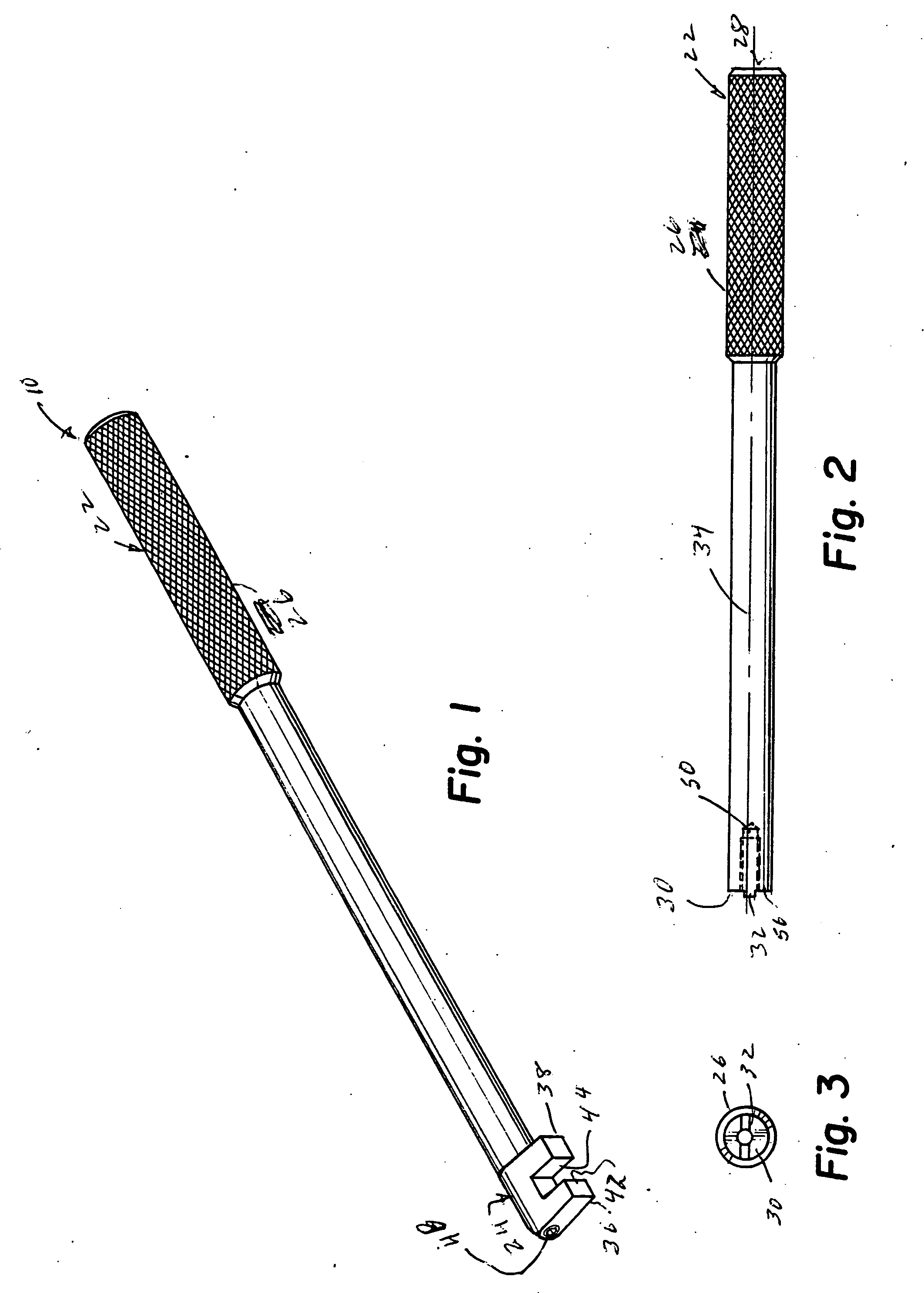
[0017] As best seen in FIGS. 1-3 and 7, tool 10 has a handle portion 22 to be held by a user of tool 10 and an engaging portion 24 adapted to grip a portion of pulley 12 and prevent pulley 12 from rotating around axis 14 when handle portion 22 is being held by the user of tool 10.

[0018] Handle portion 22 has a size and shape sufficient to extend through lines and hoses provided on a motor vehicle or automobile engine when pulley 12 is connected to water pump 16 that is being used on the engine. A diamond knurl 26 is provided on one end or holding end 28 of handle portion 22 to assist a user in gripping tool 10. At the other end or connecting end 30 of handle portion 22 is a shoulder 32 for...


PUM


Abstract

A hand held tool to prevent a pulley from rotating around an axis of rotation. A handle portion is provided on the tool to be held by a user of the tool. An engaging portion is provided to grip a portion of the pulley and prevent the pulley from rotating around the axis when said handle portion is held by the user. A tool is used to remove a fan clutch on an automobile engine. The tool has a handle portion having a user gripping portion disposed at one end and a connecting portion at another end. An engaging portion is used to grip a rim of the pulley and prevent the pulley from rotating around its rotating axis. The engaging portion has a U-shaped body with a base connected to the connecting portion of the handle portion and two arms extending radially from an axis formed by the elongated rod of the handle portion. The arms are displaced from one another by an amount sufficient to receive a rim of the pulley and have a sufficient size to form a friction surface to inhibit rotation of the pulley around its rotating axis when the arms engage the rim of the pulley.

Description

BACKGROUND OF THE INVENTION [0001] This invention relates to a hand held tool to prevent a pulley from rotating around an axis of rotation, a tool used in removing a fan clutch on an automobile engine, and a method of removing a fan clutch on an automobile engine, BRIEF SUMMARY OF THE INVENTION [0002] When the water pump on an engine of a motor vehicle; such as a car or truck, fails, it is necessary that the pulley providing the rotating power to the water pump be removed. This pulley is driven by a belt driven by a pulley connected to the vehicle engine. Frequently, this pulley also rotates a fan, which moves air through the motor vehicle's radiator. Thus, there is very little room or space between the engine and the radiator in which a mechanic has available to work in removing this pulley. [0003] Some tools have been made to prevent pulley from rotating by engaging bolts holding the pulley to the water pump, but these tools leave the mechanic less room to work and will only work ...

Claims


Application Information

Patent Timeline
IPC IPC(8): B25B13/48B25B27/00
CPCB25B27/0035B25B13/48
Inventor SMITH, GALE L.CRAWFORD, TIMOTHY A.
Owner SMITH GALE L
Learn More