
Image capture device and associated method of compensating backlash

Inactive Publication Date: 2005-01-20
RICOH KK
View PDF19 Cites 59 Cited by
  • Summary
  • Abstract
  • Description
  • Claims
  • Application Information

AI Technical Summary

Benefits of technology

[0015] In this manner, the image capture device of an exemplary embodiment of the present invention can switch between processing or omitting the backlash-removing operation according to the shooting-condition. Therefore, when it is in the shooting-condition demanding high-speed shutter-releasing response, the image capture device can shorten the necessary time for completion of the focusing operation. Otherwise, when it is in the shooting-condition that the focusing operation with high-precision is initiated by the user, the image capture device can improve the focusing precision and the user can capture images according to the shooting-condition.
[0037] In this manner, the image capture device can control an accidental error of an stopping-position of the focusing unit that may cause by the backlash by adjusting the driving-target position with predetermined travel distance as the adjustment value.

Problems solved by technology

Though the CCD-AF operation provides high focusing precision, the CCD-AF operation also has two problems.
The first problem is that necessary time to determine processing of the CCD-AF operation (i.e., necessary time to complete the AF operation) is relatively long.
Likewise, the second problem is that a user cannot capture images before the completion of the AF operation, when the user wants to capture an image having objects that move at high speed.
The CCD-AF operation may be not able to execute focusing movement adequately so that the image capture device cannot evaluate remarkable contrast of the image projected onto the image pickup unit, for example, in a dark condition having a decreased level of overall contrast.
Therefore, a stopping-position of the focusing lens group may have an accidental error in accordance with a driving direction (a push-out direction or a pull-back direction) from a current position of the focusing lens group toward the focusing position by hysteresis with backlash.
This backlash occurs even if the predetermined pulse-number to drive the focusing lens group to the predetermined push-out position is applied to the pulse motor.
On the other hand, however, the user may feel that the focusing movement is sluggish so that the increased time necessary to complete external-metering AF operation is larger than the CCD-AF operation according to the shooting-condition, when the above-mentioned backlash-removing operation is executed during the external-metering AF operation

Method used


Image

  • Image capture device and associated method of compensating backlash
  • Image capture device and associated method of compensating backlash
  • Image capture device and associated method of compensating backlash

Examples


Embodiment Construction

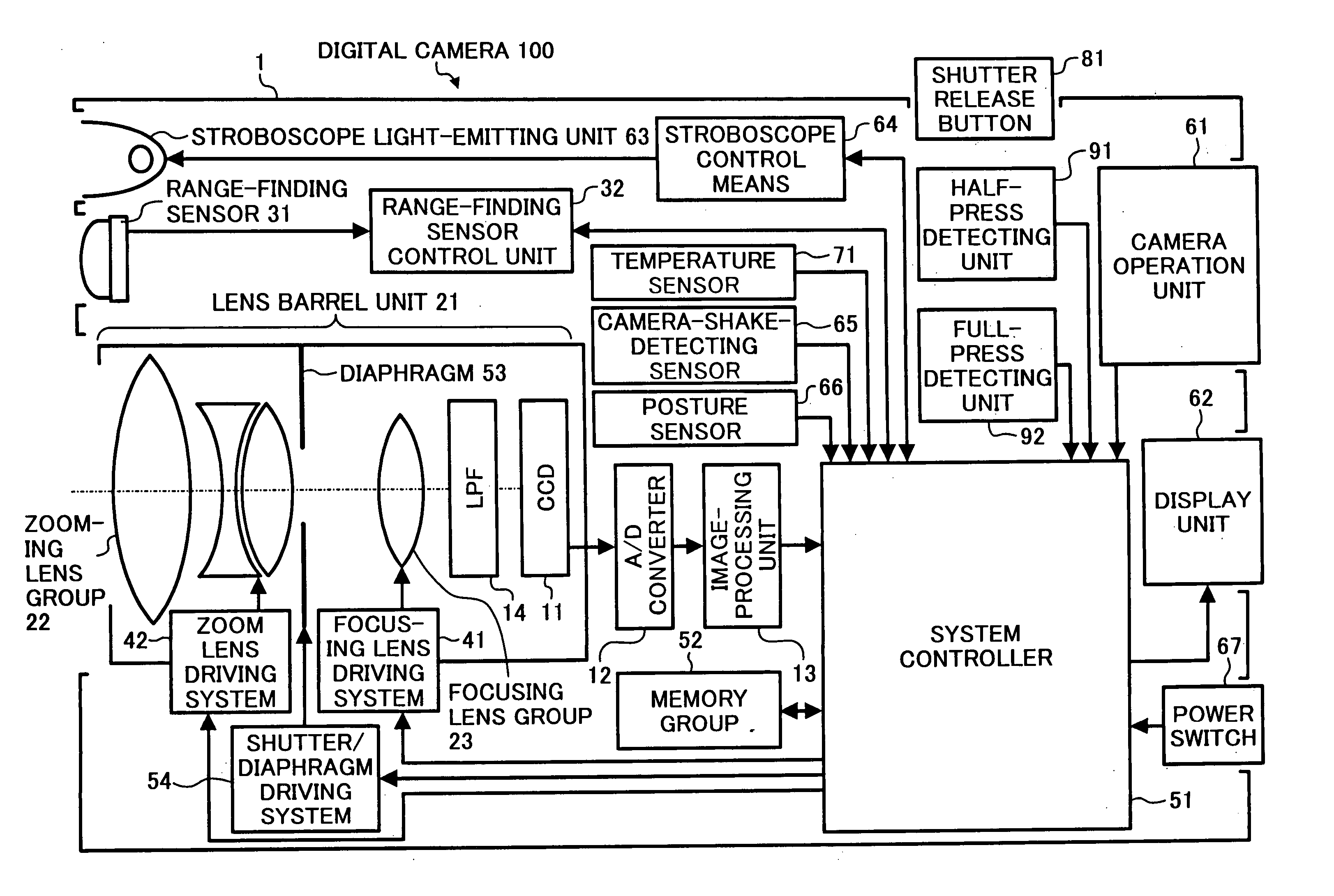
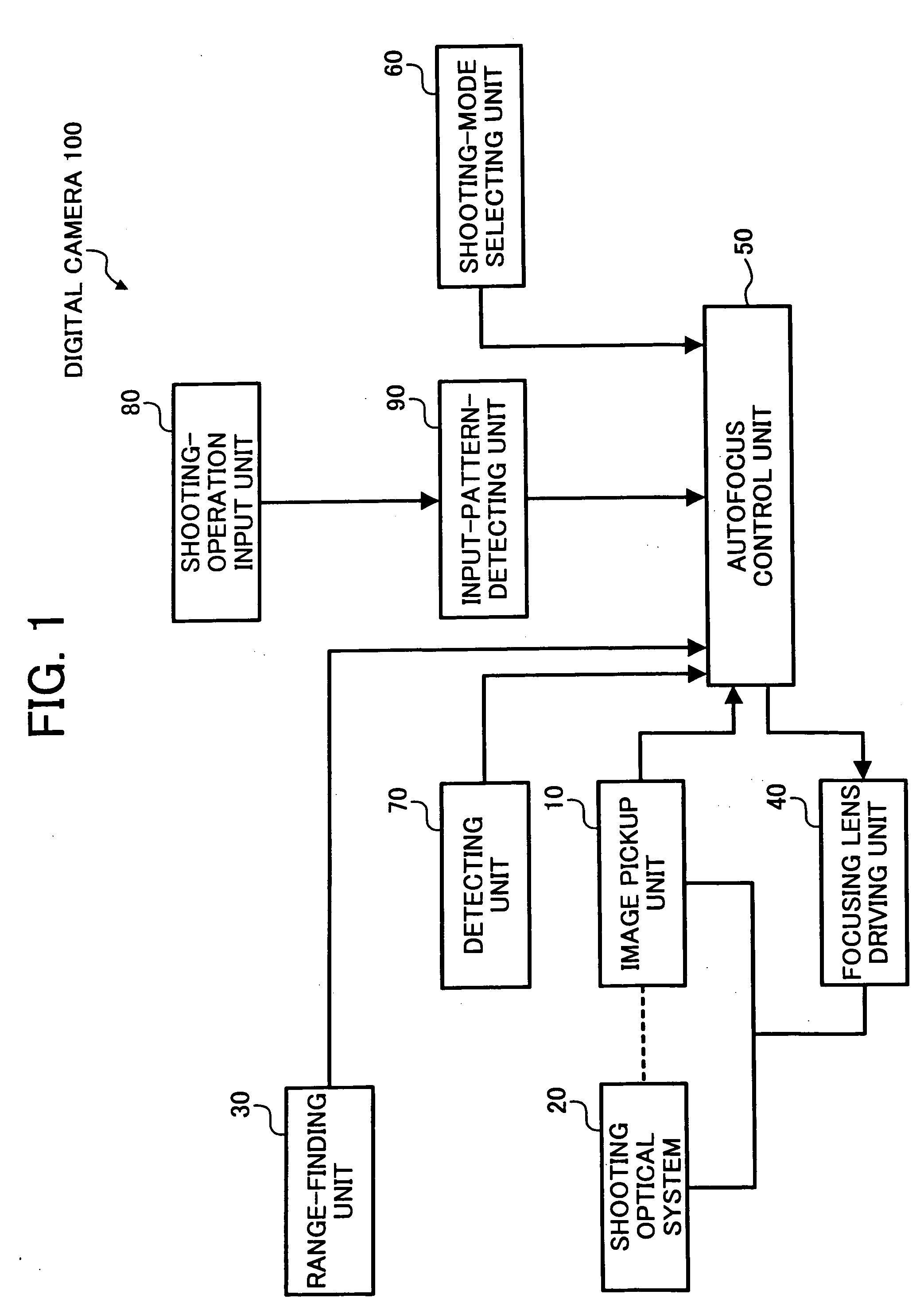
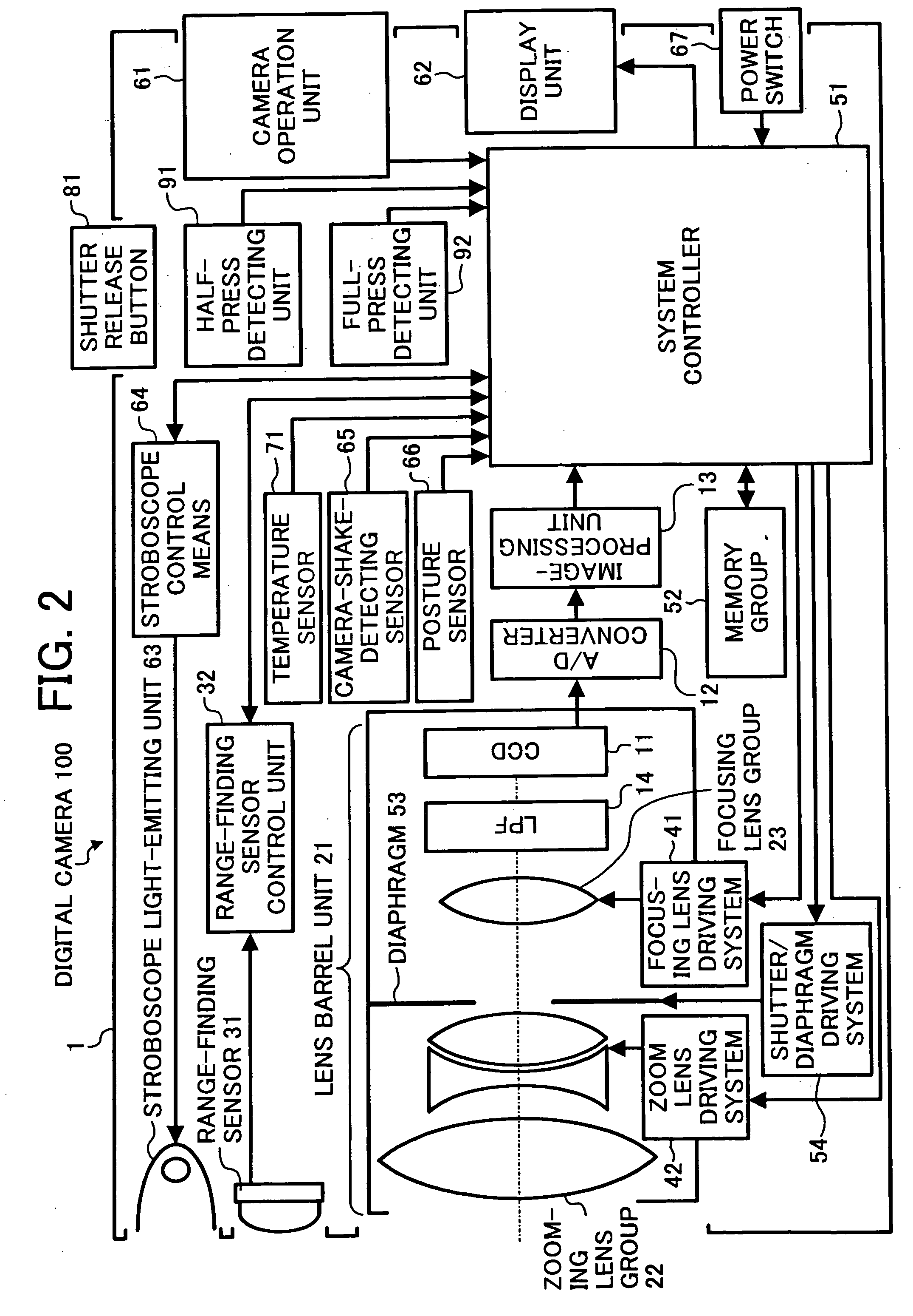
[0058] Embodiments of the present invention are now described below with reference to the drawings wherein like reference numbers designate like elements throughout. FIG. 1 shows the configuration of an image capture device according to an exemplary embodiment of the present invention.

[0059] More specifically, FIG. 1 shows a high level block diagram of a digital camera generally designated 100 of the exemplary embodiment of the invention. The digital camera 100 includes an image pickup unit 10, a shooting optical system 20, a range-finding unit 30, a focusing lens driving unit 40, autofocus control unit 50, a shooting-mode selecting unit 60, a detecting unit 70, a shooting-operation input unit 80 and an input-pattern-detecting unit 90.

[0060] The image pickup unit 10 is configured to output an image signal by converting a projected image of an object to an electrical signal. The shooting optical system 20 is configured to project the image of the object onto the image pickup unit 1...


PUM


Abstract

An image capture device includes a focusing unit, a focus driving unit and an autofocus control unit; the focusing unit is provided to focus on a subject. The focus driving unit is provided for driving the focusing unit to driving-target position. The autofocus control unit is provided to control driving of the focus driving unit according to a determination of executing or omitting a one-way-driving-control. One-way driving control controls driving direction of the focus driving unit into a predetermined direction at a peripheral range before driving-disactivation of the focus driving means, determined based on a shooting-condition.

Description

BACKGROUND OF THE INVENTION [0001] The present invention generally relates to an image capture device, such as a digital camera, and more specifically, to an image capture device having an autofocus assembly operative to diminish a backlash condition. [0002] Conventionally, the image capture device, such as a still camera and a video camera employs an autofocus assembly to automatically adjust a focus condition of an optical image of a subject. The autofocus assembly arranged in a traditional image capture device has a range-finding unit that is configured to measure a distance between the subject and the device. [0003] Additionally, the conventional device includes a focus driving unit that is arranged to drive a focusing lens group to the focusing position corresponding to the distance measured by the range-finding unit. This operation is called an external-metering AF (auto focus) operation. The external-metering AF employs two known methods of operation corresponding to differen...

Claims


Application Information

Patent Timeline
IPC IPC(8): G02B7/09G03B13/36G02B7/10G02B7/28G03B17/38H04N5/232
CPCH04N5/23212G02B7/102H04N23/672H04N23/673
Inventor SHINOHARA, JUNICHI
Owner RICOH KK
Learn More