Adaptive coring for video peaking

a coring and video technology, applied in the field of video signal processing, can solve the problems of difficult to achieve optimal peaking and noise coring, prior art solutions, visible distortion in the displayed video image, etc., and achieve the effect of increasing the chance of coring and noise more readily visibl

Active Publication Date: 2005-01-20
STMICROELECTRONICS ASIA PACIFIC PTE
View PDF2 Cites 28 Cited by
  • Summary
  • Abstract
  • Description
  • Claims
  • Application Information

AI Technical Summary

Benefits of technology

[0014] Preferably, the luminance gradients within the first range are smaller than the luminance gradients within the second range, and, the luminance gradients within the second range are smaller than the luminance gradients within the third range. Advantageously, the order of the ranges enables peaking of small details in images without over-enhancing larger details.
[0017] Preferably, the present invention includes a means for measuring an average luminance of pixels within the inter-pixel array, wherein, the gain function of the gain adjustment circuit is adjustable relative to the measured average luminance. Also preferably, the gain function of the gain adjustment circuit is adjustable relative to the measured average luminance, whereby the first range of luminance gradients attenuated by the gain function increases relative to a decrease in the measured average luminance. Advantageously, the present invention adjusts the gain function of the gain adjustment circuit to increase the chance of coring relatively darker regions of the input luminance signal where noise is more readily visible. Conversely, for regions of the input luminance signal having relatively strong luminance, the gain function is adjusted whereby the region of the input luminance signal is more likely to be peaked.

Problems solved by technology

However, prior art solutions are problematic in that, whilst they enhance the edge components of a video signal, they also tend to amplify noise components of the signal which occupy the same frequency range.
This results in visible distortion in the displayed video image.
Moreover, the noise characteristics of a video signal may vary throughout the signal, and prior art peaking techniques are not sensitive to these fluctuations meaning that optimal peaking and noise coring is difficult to achieve.
Another problem inherent in prior art inventions is that they are unable to scale the filtered signal such that weak edges are enhanced without over-enhancing strong edges.
However, these filters tend to leave residual chroma in the luminance signals which is susceptible to peaking and appears as moving noise when peaked.

Method used


Image

  • Adaptive coring for video peaking
  • Adaptive coring for video peaking
  • Adaptive coring for video peaking

Examples


Embodiment Construction

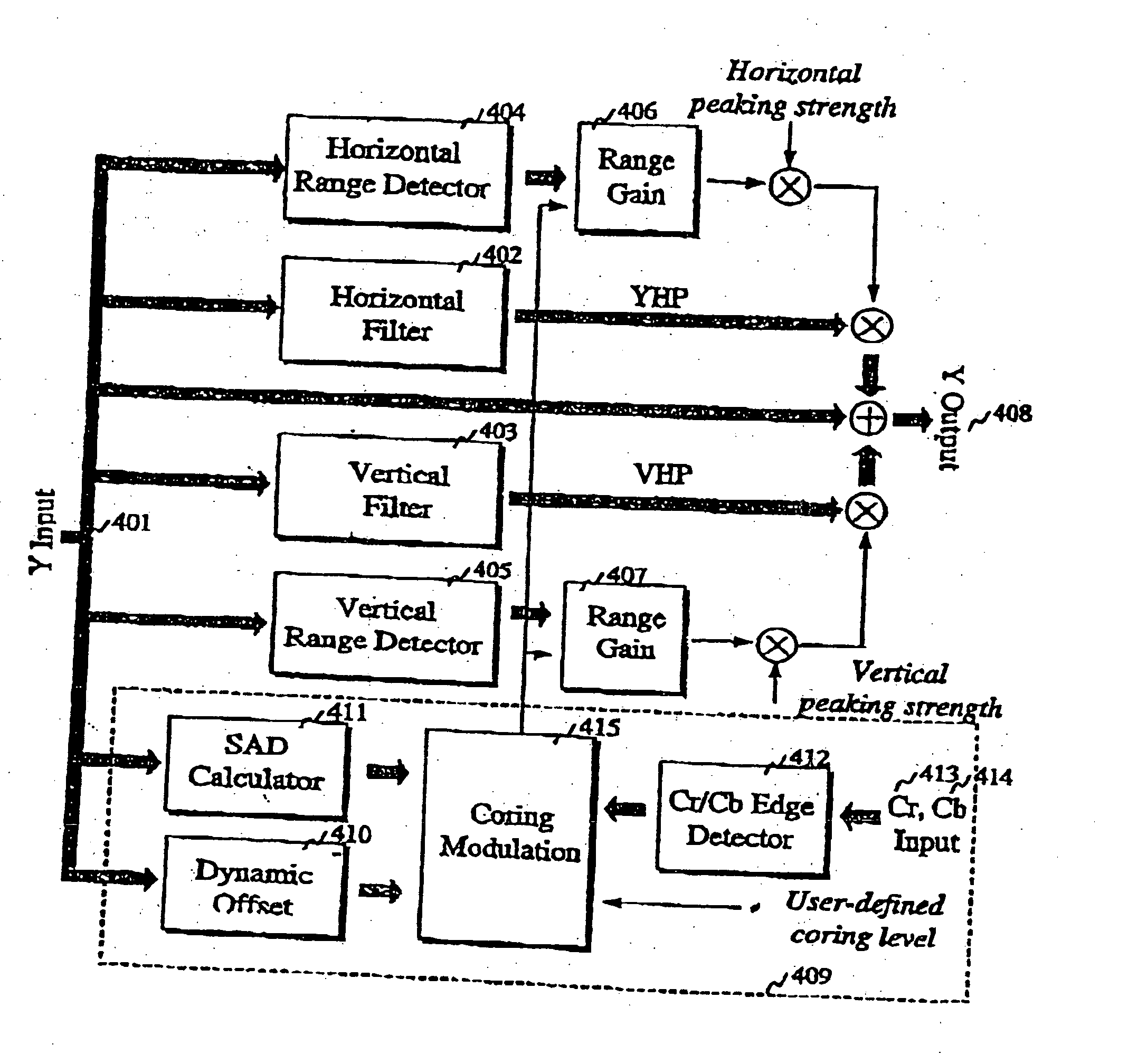
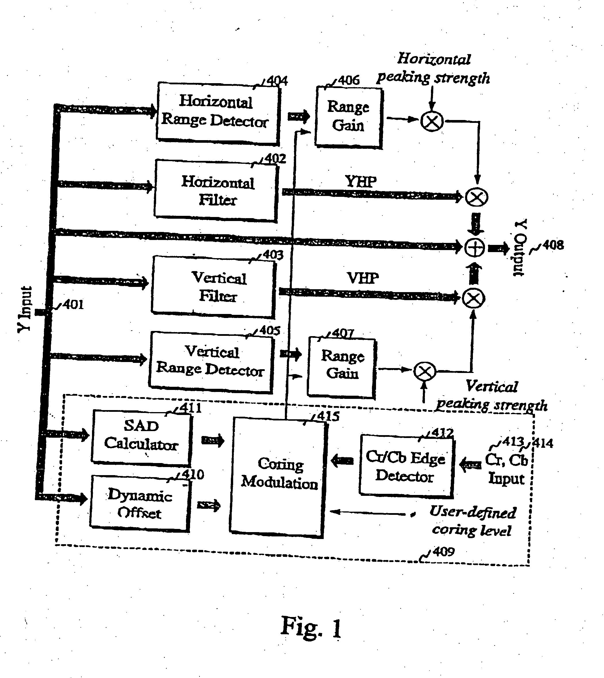
[0032] Throughout the specification, the term “peaking” refers to an image enhancement technique whereby “edges” or transition areas within an image are sharpened by selectively emphasizing frequency components of a signal which represents the image. The term “peaking filter” refers to a filter which may emphasize selected frequency bands of a signal relative to other frequency bands within the signal. The term “coring” refers to the suppression of peaking effects across specific frequency components of a signal and is typically employed to minimize the enhancement of noise components within the input luminance signal.

[0033]FIG. 1 illustrates a first embodiment of the present invention for processing an input luminance signal (401) such as is produced by a composite signal decoder, an MPEG decoder, or the like. In the present embodiment, the input luminance signal (401) represents a stream of pixel luminance values corresponding to pixels which comprise a two-dimensional image for ...


PUM


Abstract

A processor for enhancing an input luminance signal including: a means for calculating a chroma edge value associated with the input luminance signal; a means for measuring a luminance gradient associated with the input luminance signal; a peaking filter for processing the input luminance signal; a gain adjustment circuit having a gain function that is adjustable relative to the calculated chroma edge value, the gain adjustment circuit being operable to adjust the magnitude of the output of the peaking filter wherein: in a first range of luminance gradients, the output is an attenuated version of the input; in a second range of luminance gradients the output is directly proportional to the input; in a third range of luminance gradients, the output is inversely proportional to the input; wherein said enhanced luminance signal is the sum of the input and output of the peaking filter.

Description

BACKGROUND OF THE INVENTION [0001] 1. Field of the Invention [0002] The present invention relates to video signal processing and in particular to a means of enhancing the sharpness of video images. [0003] 2. Description of the Related Art [0004] Video peaking techniques have been used to enhance the sharpness of video images. Conventional video peaking techniques typically involve enhancing the “edges” or transition regions within an image by filtering a luminance signal with a high-pass or band-pass filter, scaling the filtered signal with a gain factor, then adding the scaled signal with the original luminance signal to generate an output signal having sharper edges. [0005] Prior art inventions also tend to involve the use of peaking techniques in combination with noise coring techniques which is the process by which a range of signal levels are suppressed (i.e., are not peaked) so as to avoid amplifying the visible noise in the signal. [0006] For instance, prior art document U.S....

Claims


Application Information

Patent Timeline
Patent Type & Authority Applications(United States)
IPC IPC(8): G06T5/00G06T5/20H04N5/14H04N5/21H04N9/77
CPCG06T5/20H04N5/142H04N5/21H04N9/77G06T2207/20192G06T7/0085G06T2207/10016G06T2207/10024G06T2207/20012G06T5/003G06T7/13
Inventor CHIANG, PATRICIA WEI YINHUI, LUCAS Y.W.
Owner STMICROELECTRONICS ASIA PACIFIC PTE
Why Eureka
Try Eureka