Method for predicting a future voltage and/or current curve

a technology of voltage and current curve and prediction method, which is applied in the direction of relays, circuit-breaking switches, transportation and packaging, etc., can solve the problems of voltage spikes, changes in the periodicity of current and voltage or else transient processes, and the calculation that is required for this purpose is associated with a considerable time requiremen

Inactive Publication Date: 2005-01-20
SIEMENS AG
View PDF2 Cites 10 Cited by
  • Summary
  • Abstract
  • Description
  • Claims
  • Application Information

AI Technical Summary

Problems solved by technology

In addition, voltage spikes and changes in the periodicity of the current and voltage or else transient processes can occur as a result of unpredictable events, such as switching overvoltages, which are produced when switching processes take place in th...

Method used


Image

  • Method for predicting a future voltage and/or current curve
  • Method for predicting a future voltage and/or current curve
  • Method for predicting a future voltage and/or current curve

Examples


Embodiment Construction

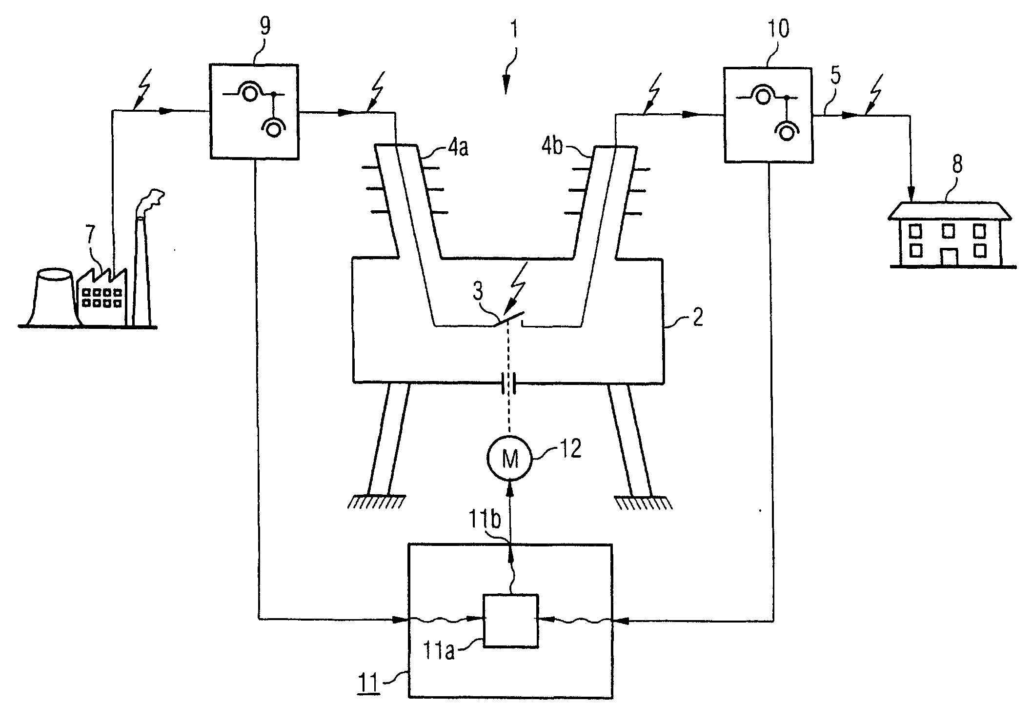
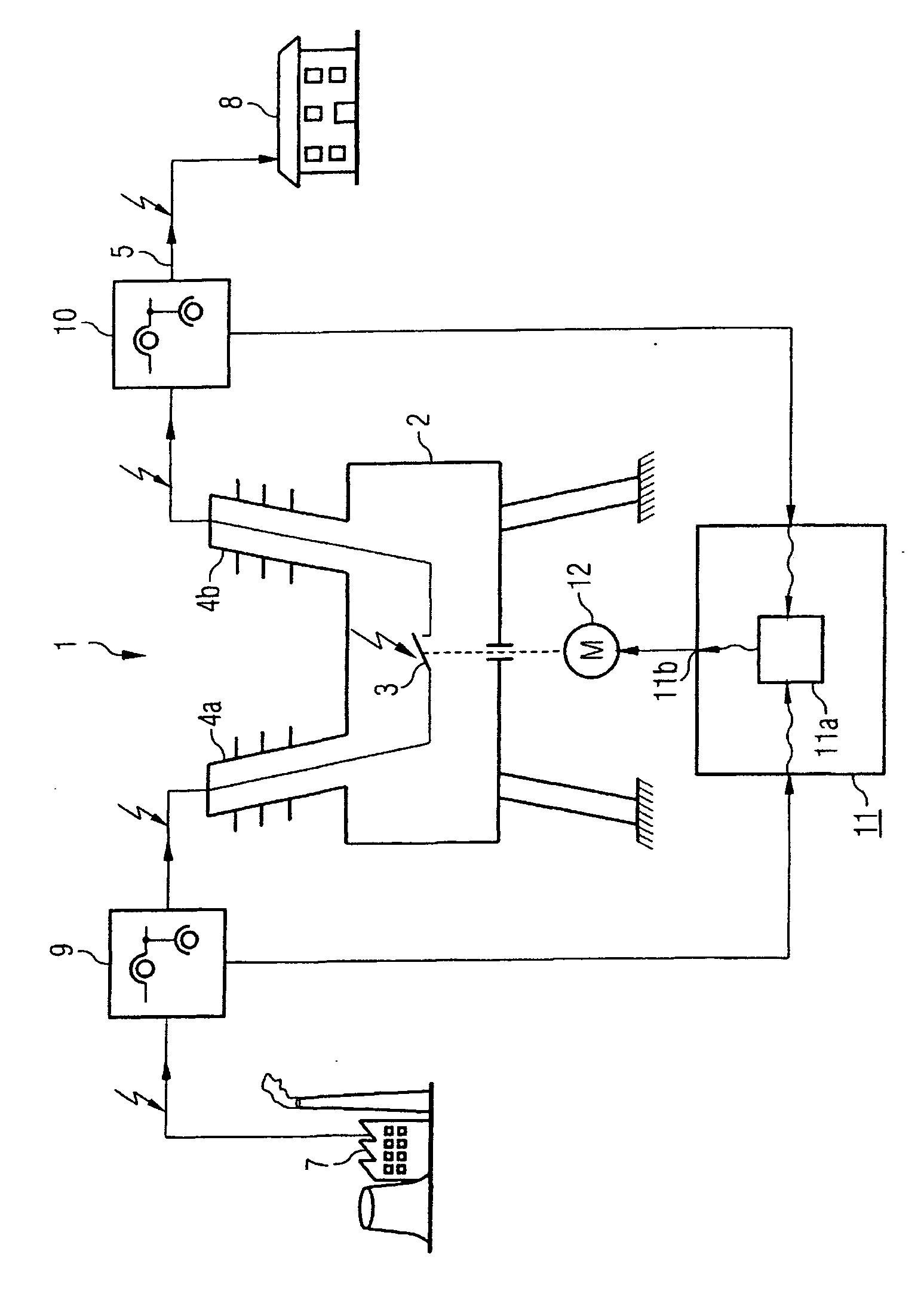
FIG. 1 shows a section through a schematically illustrated high-voltage circuit breaker 1. The high-voltage circuit breaker 1 has encapsulation 2 in which an interrupter unit 3 for the high-voltage circuit breaker 1 is arranged. The interrupter unit 3 for the high-voltage circuit breaker 1 is connected to an electrical power supply system 5 by means of high-voltage bushings 4a, b. The electrical power supply system 5 may, for example, be an overhead line power supply system for transmitting electrical power from a power station 7 to a consumer 8. A first measurement apparatus 9 is arranged upstream of the high-voltage circuit breaker 1 in the power flow direction. A second measurement apparatus 10 is arranged downstream from the high-voltage circuit breaker 1 in the power flow direction. The first measurement apparatus 9 and the second measurement apparatus 10 may, for example, comprise current transformers and voltage transformers as well as further apparatuses. It is also possible...


PUM


Abstract

According to the invention, a controlled or synchronous switching of an electrical power breaker (1) can be guaranteed by means of predicting a future voltage and/or current curve from actual voltage and/or current data in an electrical energy network (5). The prediction of the future voltage and/or current curve is carried out using the voltage and/or current data determined in the electrical network (5) at different timepoints by application of a Prony method to the available voltage and/or current data.

Description

CLAIM FOR PRIORITY This application claims priority to International Application No. PCT / DE02 / 04573 which was published in the German language on Jun. 19, 2003, which claims the benefit of priority to German Application No. 101 62 118.3, which was filed in German language on Dec. 12, 2001. TECHNICAL FIELD OF THE INVENTION The invention relates to a system and method for determination of a future voltage and / or current waveform in an electrical power supply system. BACKGROUND OF THE INVENTION In electrical power supply systems, in particular power supply systems for the transmission of electrical power whose voltage changes periodically and in which the current flowing through the power supply system changes periodically, it is desirable to be able to predict future voltage and / or current waveforms. During undisturbed operation, the voltage and the current oscillate periodically at a constant frequency, with a constant amplitude, about a defined zero position. A phase shift can oc...

Claims


Application Information

Patent Timeline
IPC IPC(8): H01H9/56H01H33/59H02H1/00H02J3/00
CPCH02H1/0092H01H9/56H02H3/021
Inventor PILZ, GEORGSCHEGNER, PETER
Owner SIEMENS AG
Why Eureka
Try Eureka