Multiple wavelength photonic oscillator

Inactive Publication Date: 2005-01-20
HRL LAB
View PDF68 Cites 38 Cited by
  • Summary
  • Abstract
  • Description
  • Claims
  • Application Information

AI Technical Summary

Benefits of technology

[0011] The effect of the feedback loop is to delay the RF modulated optical signal at a control wavelength, convert that signal into a RF electrical signal and use that delayed electrical signal to drive the optical modulator. When the gain of the feedback loop is greater than one, oscillation occurs. In contrast to the prior approaches, this RF feedback signal modulates light at multiple optical wavelengths. The time delays from the various paths of the feedback loop determine the frequency or frequencies of the modulation. The filters in the loop determine the number of modulation frequencies or tones. The RF modulations on the various optical wavelengths are coher

Problems solved by technology

The disadvantage of this prior approach is its need for a separate electronic oscillator, which can be costly if low phase noise is required.

Method used


Image

  • Multiple wavelength photonic oscillator
  • Multiple wavelength photonic oscillator
  • Multiple wavelength photonic oscillator

Examples


first embodiment

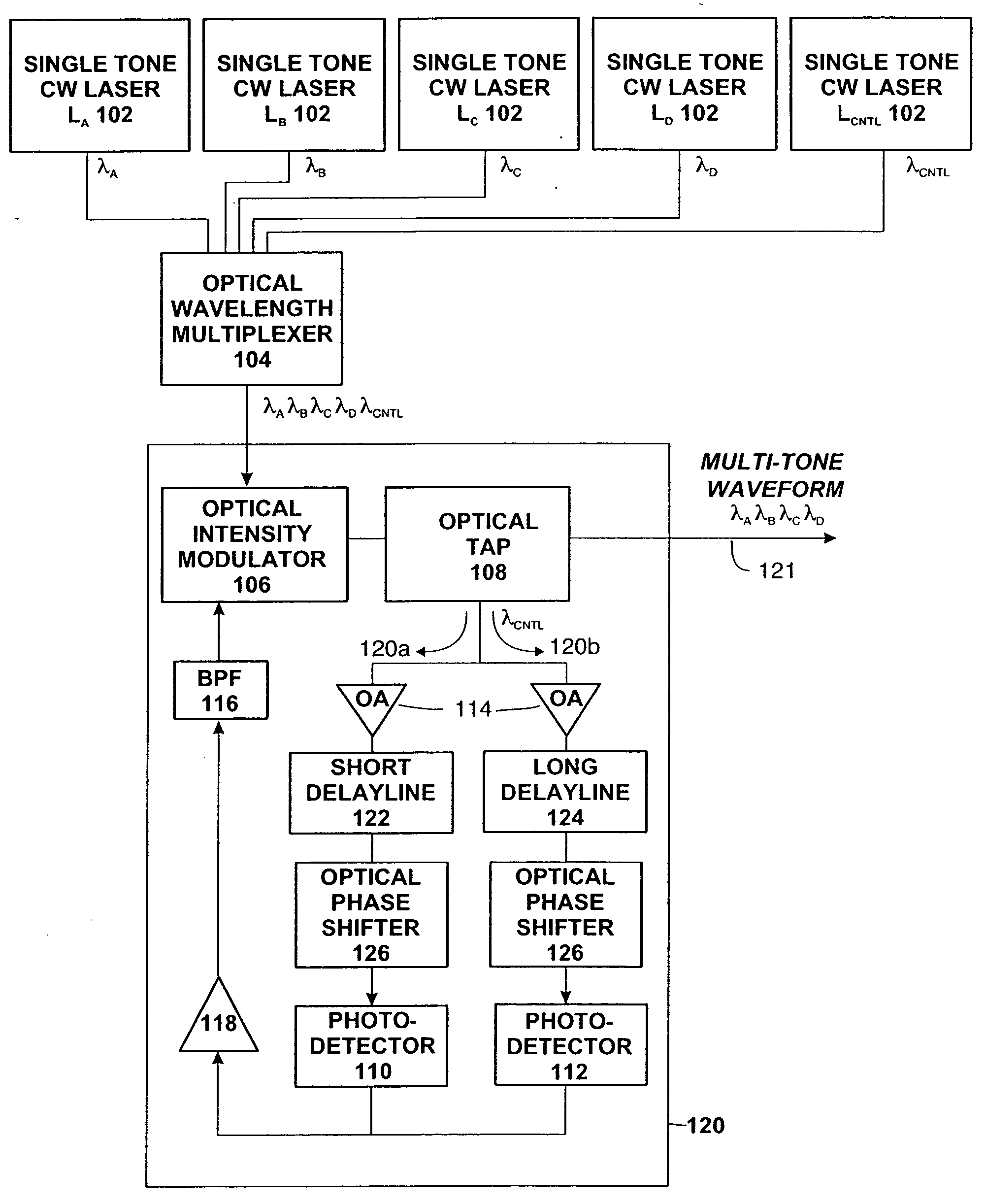
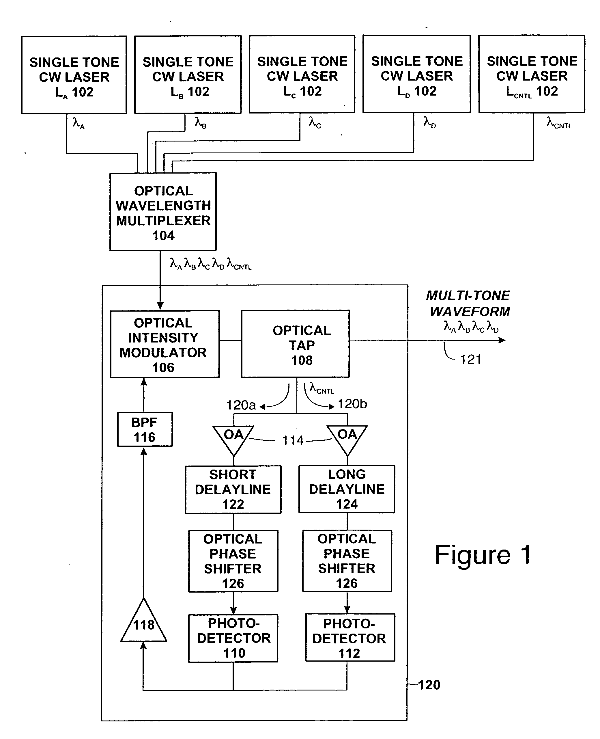
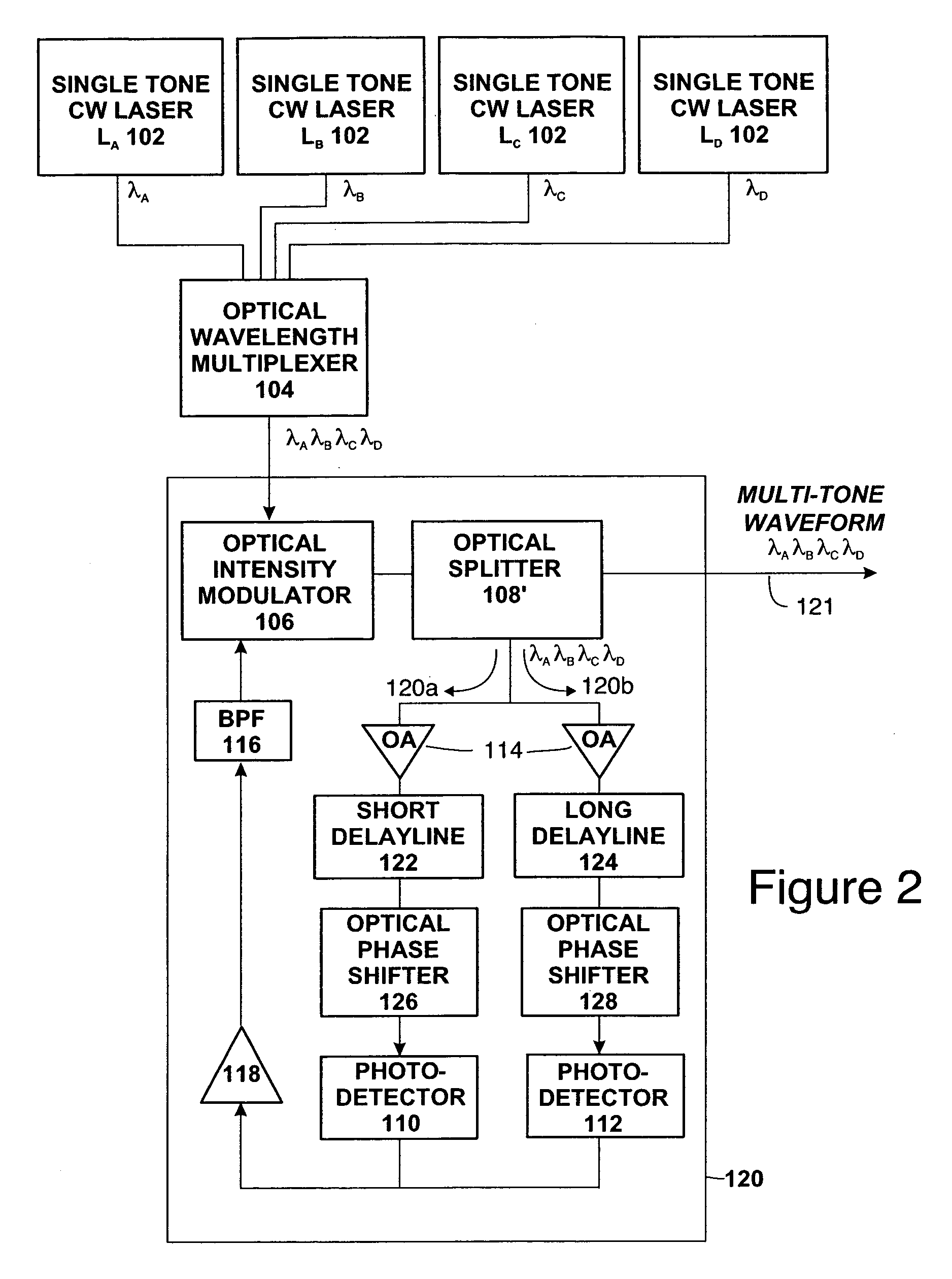
[0030] Another embodiment of the MWPO 100 is illustrated in FIG. 2. This MWPO 100 comprises multiple lasers 102 (which emit at different wavelengths or optical frequencies), an optical wavelength multiplexer 104, an optical modulator 106 and photodetectors 110 and 112 connected as a closed feedback loop 120. The loop 120 optionally includes optical amplifiers 114 and / or electronic amplifiers 118, optical phase shifters 122, 124 and / or electronic phase shifters (not shown, but would occur in the electronic portion of the loop) and filters 116. A portion of the laser light in all of the laser wavelengths (e.g., λA, λB, λC, λD) is diverted into the feedback path 120 by an optical splitter 108′. The remaining portion of the laser light in all of the wavelengths is provided as an output 100a of the MWPO 110. These wavelengths can be associated with and supplied to various pairs of laser diodes for optical injection locking (as illustrated in FIG. 5). They also can be associated with vari...

second embodiment

[0031] The main distinction between the two embodiments of FIGS. 1 and 2 is that in the second embodiment all of the wavelengths are coupled into the feedback loop 120. Thus, the total amount of optical power carried in the loop determines that total photodetector current for the loop. The optical splitter 108′ controls the amount of power diverted into the loop 120. Note that the optical amplifiers 114, optical phase shifters 126, 128 and photodetectors 110, 112 must be compatible with the various wavelengths of the light coupled into the loop 120.

[0032] The reason that this second embodiment is less preferred than the first embodiment is the increased constraints this embodiment places on the wavelengths and powers of the lasers 102. Otherwise, both embodiments should provide suitable signals for the various applications described herein.

[0033] In the case of the first embodiment, the only restriction placed on the lasers LA-LD that supply the light wavelengths that are output fr...


PUM


Abstract

A multi-wavelength photonic oscillator has a plurality of lasers each emitting light at a different frequency. An optical wavelength multiplexer combines the light emitted by the plurality of lasers at an output thereof as a set of optical wavelengths. An optical modulator is arranged in a feedback loop and coupled to receive light at the output of the optical wavelength multiplexer, the feedback loop further including an optical tap for coupling at least a subset of said set of optical wavelengths to at least one optical output of the multi-wavelength photonic modulator; at least one optical channel having an associated photodetector arranged to receive light from the optical tap via the at least one optical channel; and an electronic loop portion coupled to receive output from the at least one associated photodetector and to provide an input for the optical modulator.

Description

CROSS REFERENCE TO RELATED APPLICATION [0001] This application claims the benefit of U.S. Provisional Patent Application No. 60 / 487,534 filed Jul. 14, 2003, the disclosure of which is hereby incorporated herein by reference.TECHNICAL FIELD [0002] This invention provides a multi-wavelength photonic oscillator (MWPO) that generates a multi-wavelength optical waveform in which each wavelength is amplitude modulated with a common low noise RF tone or family of tones. BACKGROUND OF THE INVENTION [0003] The invention extends the prior concepts of a multi-tone photonic oscillator and of a single-tone opto-electronic oscillator to multiple optical wavelengths. The prior approaches supply only a single optical wavelength. Using these prior approaches, a multiple wavelength output would require multiple oscillators, with each oscillator operating at a different optical wavelength. If those oscillators have RF tones of nominally the same frequency modulated onto the optical carrier, the RF sig...

Claims


Application Information

Patent Timeline
IPC IPC(8): G02F2/00H04B10/155H04J14/00H04J14/02
CPCG02F2/002H04B10/50572H04J14/0298H04B10/506H04J14/02H04B10/50577
Inventor YAP, DANIEL
Owner HRL LAB
Why Eureka
Try Eureka