
Intraocular lens system

Active Publication Date: 2005-01-20
ALCON INC
View PDF18 Cites 32 Cited by
  • Summary
  • Abstract
  • Description
  • Claims
  • Application Information

AI Technical Summary

Benefits of technology

[0009] Accordingly, one objective of the present invention is to provide a safe and biocompatible intraocular lens.
[0010] Another objective of the present invention is to provide a safe and biocompatible intraocular lens that is easily implanted in the posterior chamber.
[0011] Still another objective of the present invention is to provide a safe and biocompatible intraocular lens that is stable in the posterior chamber.
[0012] Still another objective of the present invention is to provide a safe and biocompatible adjustable lens system.
[0013] Still another objective of the present invention is to provide a safe and biocompatible lens system that can be implanted through a small incision.
[0014] Still another objective of the present invention is to provide a safe and biocompatible lens system that helps reduce the incidence of PCO.

Problems solved by technology

When age or disease causes the lens to become less transparent, vision deteriorates because of the diminished light which can be transmitted to the retina.
The fixed increment of the lens, and the slight variation in lens placement can result in less than optimum vision.
If the power of the implanted lens is incorrect, removal and exchange of a new lens is difficult because of fibrosis of the lens haptics within the capsular bag.
The multi-lens designs and the threadedly adjustable designs are not optimized for the reduction or elimination of posterior capsule opacification (PCO).

Method used


Image

  • Intraocular lens system
  • Intraocular lens system
  • Intraocular lens system

Examples


Embodiment Construction

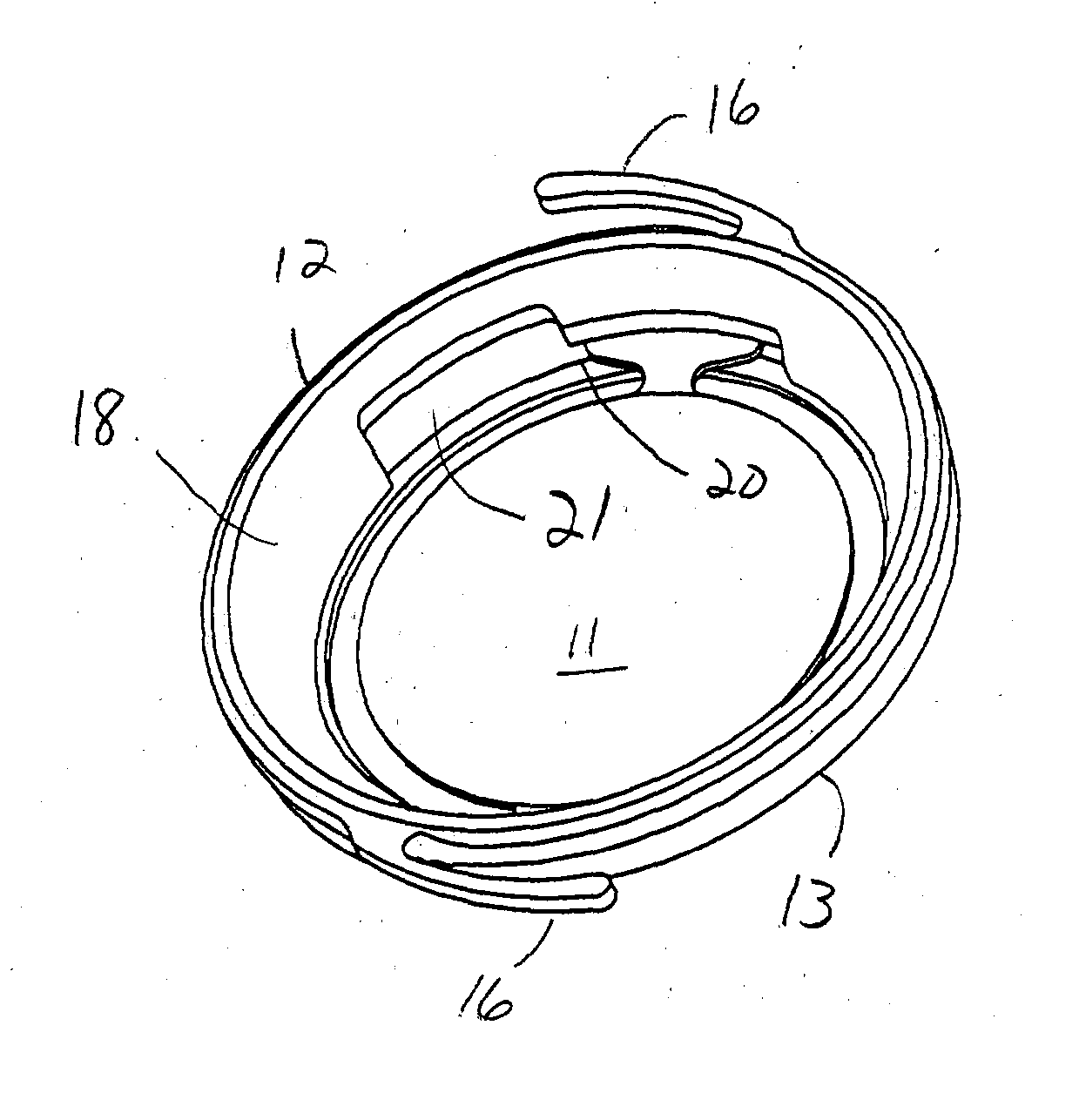
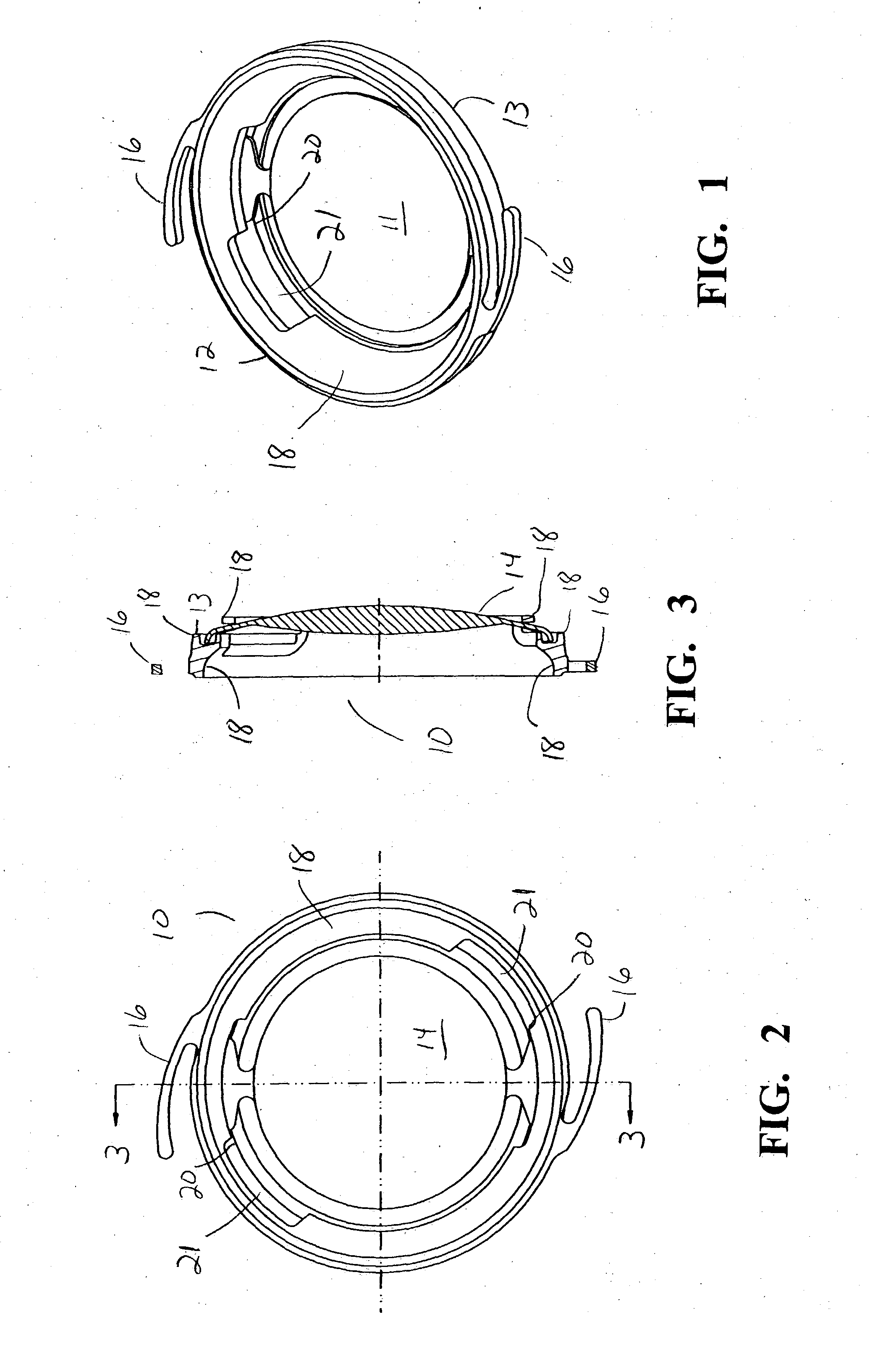
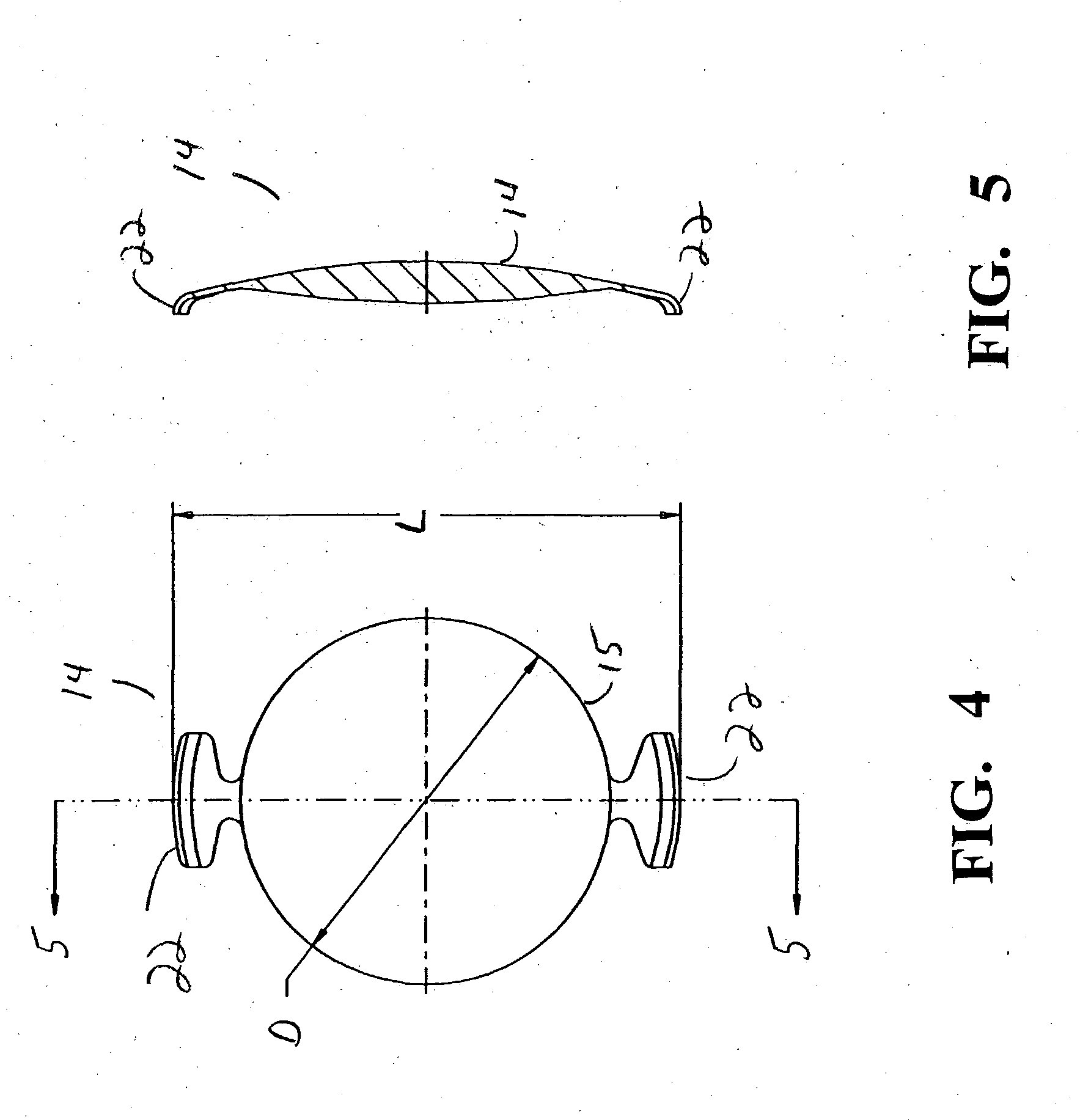
[0021] As best seen in FIGS. 1-3, lens system 10 of the present invention generally consists of first, or base, component 12 and second, or optical, component 14. Base component 12 is generally ring-like, having hollow center 11 and contains a plurality of integrally formed haptics 16 and is preferably formed in any suitable overall diameter, for example, between approximately 10.0 millimeters and 12.0 millimeters, a suitable interior diameter, for example, between approximately 7.0 millimeters and 9.0 millimeters and made from a soft, foldable material such as a soft acrylic. Alternatively, base component 12 may be made from a material that is stiffer relative to optical component 14. Preferably, base component 12 is constructed so as to allow it to be compressed and inserted into an eye through an incision of approximately 2.5 mm. Base component 12 may also be formed so as to be opaque, such as by frosting or texturing the anterior and / or posterior surfaces of base component 12. B...


PUM


Abstract

A two part lens system. The first part is a ring-like supporting component that is implanted in the capular bag following cataract surgery. The first component is a non-optical component and contains a pair of haptics for fixating the first component within the capular bag. The second component is an optical component that contains all of the corrective optical power of the lens system. The second component has a pair of tabs for locking the second component within the first component.

Description

BACKGROUND OF THE INVENTION [0001] This invention relates generally to the field of intraocular lenses (IOL) and, more particularly, to multi-lens IOLs. [0002] The human-eye in its simplest terms functions to provide vision by transmitting light through a clear outer portion called the cornea, and focusing the image by way of a crystalline lens onto a retina. The quality of the focused image depends on many factors including the size and shape of the eye, and the transparency of the cornea and the lens. [0003] When age or disease causes the lens to become less transparent, vision deteriorates because of the diminished light which can be transmitted to the retina. This deficiency in the lens of the eye is medically known as a cataract. An accepted treatment for this condition is surgical removal of the lens and replacement of the lens function by an artificial intraocular lens (IOL). [0004] In the United States, the majority of cataractous lenses are removed by a surgical technique c...

Claims


Application Information

Patent Timeline
IPC IPC(8): A61F2/16
CPCA61F2/1648A61F2/1613A61F2250/006A61F2220/0033A61F2002/169
Inventor TRAN, SON TRUNG
Owner ALCON INC
Learn More