Method for feeding hydroforming presses, and device for carrying out the method

a technology for hydroforming presses and presses, which is applied in the direction of metal-working holders, supporters, positioning apparatuses, etc., can solve the problems of long cycle time, rings are at risk of changing positions, and it is impossible to rule out the possibility of the position changing when the die is made, so as to achieve accurate and immovable positioning of parts.

Active Publication Date: 2005-01-27
FURCHHEIM BODO
View PDF4 Cites 4 Cited by
  • Summary
  • Abstract
  • Description
  • Claims
  • Application Information

AI Technical Summary

Benefits of technology

[0062] The upper and lower parts of the mounting device are connected to one another in a readily releasable manner by means of known locating elements. Passages, which are connected to a vacuum generator via flexible lines, are formed at certain locations in the lower part and/or upper part of the mounting device for accurate, immovable positioning of the part

Problems solved by technology

The process itself, the hydroforming operation, takes place in an extremely short time, but the ancillary times, in particular the feeding of the hydroforming press, are lengthy, which ultimately means that the cycle time is long.
An additional factor is that the position of some cam rings, on account of their shape, is very labile, and in particular these rings are at risk of changing position.
Even if a correct, functionally appropriate position of the cam rings is checked using gauges or other checking means after they have been placed into the hydroforming press, it is impossible to rule out the possibility of the position changing when the die is closed.
A change in position of just one cam ring has serious consequences.
The cam rings are hardened, and if they are incorrectly positioned in the mold nest they will destroy the die and will also be damaged themselves, rendering them unusable.
Of

Method used


Image

  • Method for feeding hydroforming presses, and device for carrying out the method
  • Method for feeding hydroforming presses, and device for carrying out the method
  • Method for feeding hydroforming presses, and device for carrying out the method

Examples


Embodiment Construction

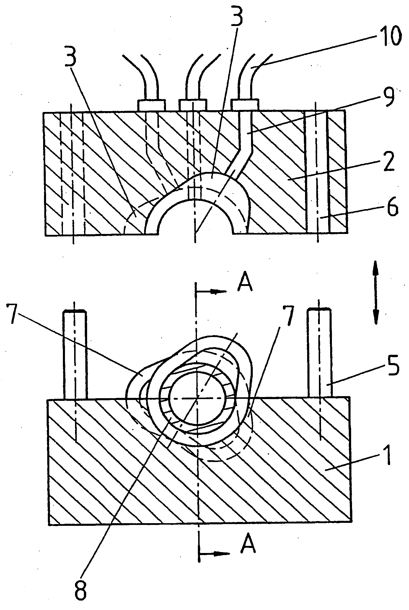
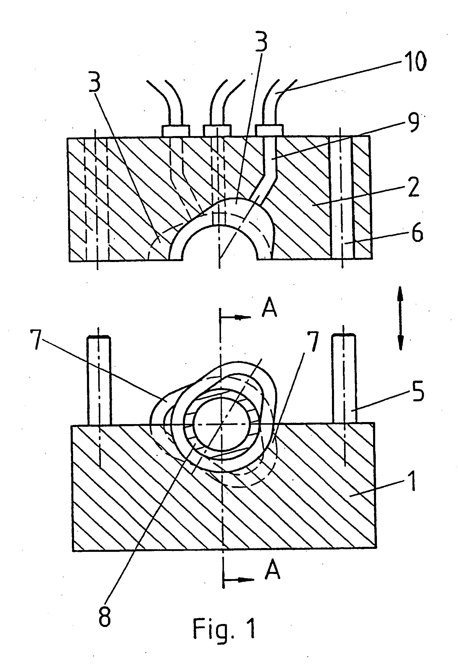
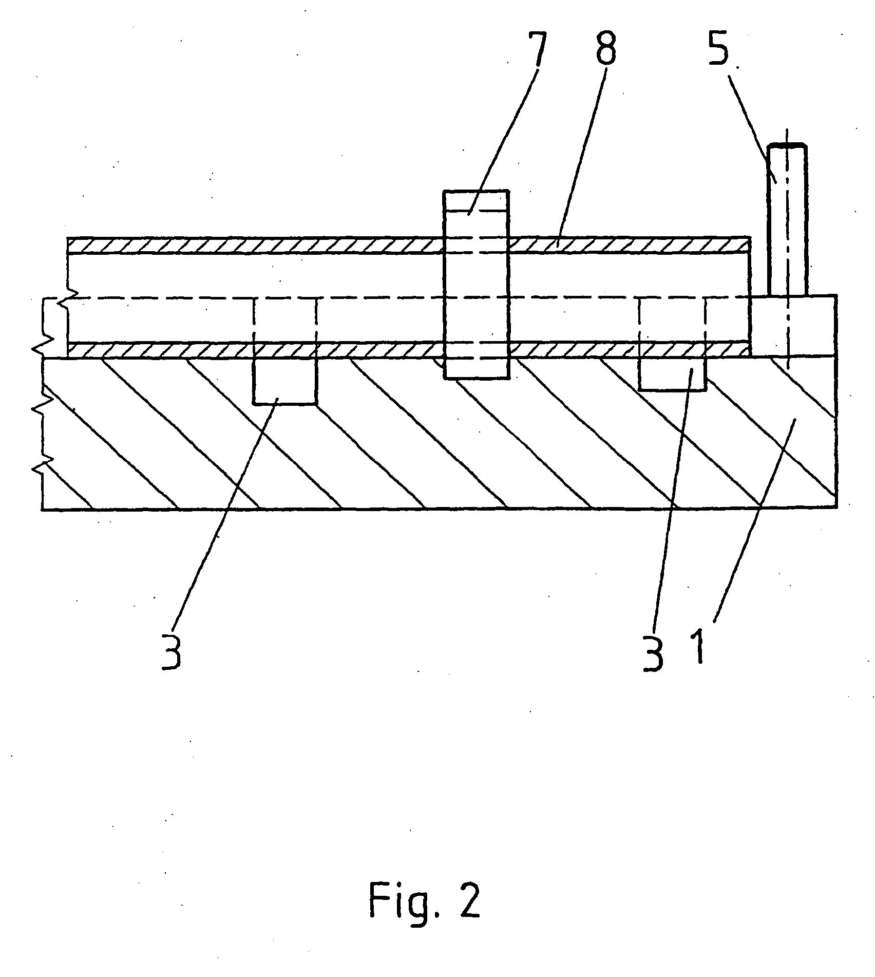
[0068] The mounting device comprises a lower part 1 and an upper part 2 and is illustrated in an open state in FIGS. 1 and 2. Mold nests 3, which are identical to the mold nests 3′ in a lower die 4 and upper die (cf. FIG. 3) of a hydroforming press, are formed in these upper and lower parts. The two parts of the mounting device are fitted accurately above one another using locating pins 5 which latch into the bores 6. The mold nests 3 and 3′ are machined out so as to correspond to the functionally related position and attitude of the cam rings 7 and hollow shaft 8. To hold the inserted parts, the hollow shaft 8, and, on it, the cam rings 7, in the correct angular position 7 after they have been put in place (in particular if the lower part 1 is removed in order for the loaded upper part 2 to be placed onto the lower die 4 of the hydroforming press), passages 9, which are connected to a vacuum generator via flexible hoses 10, are provided in the upper part 2 of the mounting device. T...


PUM

PropertyMeasurementUnit
Pressureaaaaaaaaaa

Abstract

The invention concerns a method whereby components are arranged in a mounting device, outside an internal high-pressure forming press, in accordance with their position and their function, such that they are linked to one another. The mounting device comprises an upper part and a lower part including cavities identical to the cavities of the internal high pressure tool. Once the components have been installed, the mounting device is introduced in the internal high-pressure press, then the upper part or the lower part of the mounting device is withdrawn, the part of the mounting device remaining in the internal high-pressure press being displaced against the upper tool or the lower tool. For the forming process, the components are maintained in a part of the tool by depression or by clamping, then the part of the mounting device is removed from the internal high-pressure press, thereby ensuring high precision positioning of components. Additionally, the production rate is substantially increased. The invention is particularly applicable for the production of cam shafts.

Description

CROSS REFERENCE TO OTHER APPLICATIONS [0001] The present application is a continuation of pending international patent application PCT / DE02 / 03746, filed Oct. 4, 2002 which designates the United States and was published in German, and which claims priority of German patent application 101 50 092.0, filed Oct. 11, 2001.BACKGROUND OF THE INVENTION [0002] The invention relates to a method for feeding hydroforming presses (internal high pressure forming presses) in order to produce workpieces which are composed of a plurality of parts, preferably camshafts, in a hydroforming process which is known per se. The hydroforming process is used to nonpositively and positively connect cam rings and also other components, such as drive elements, to one another. The hydroforming press which carries out the method is equipped to receive at least one workpiece, i.e. a camshaft which comprises a hollow shaft with the cam rings which are to be applied to it. [0003] The hydroforming process generally c...

Claims


Application Information

Patent Timeline
IPC IPC(8): B21D26/033B21D53/84F01L1/047
CPCB21D26/033B21D43/18B21D53/845F01L1/047Y10T29/17Y10T29/49293Y10T29/49805Y10T29/49902Y10T29/53Y10T29/49901
Inventor FURCHHEIM, BODO
Owner FURCHHEIM BODO
Why Eureka
Try Eureka