Filter

a filter and filter body technology, applied in the field of filters, can solve the problems of increased pressure loss of filters, serious problems, contamination of the environment and human body, etc., and achieve the effect of increasing the capacity of the collecting portion of filters and low pressure loss

Active Publication Date: 2005-01-27
IBIDEN CO LTD
View PDF37 Cites 103 Cited by
  • Summary
  • Abstract
  • Description
  • Claims
  • Application Information

AI Technical Summary

Benefits of technology

[0043] The present invention has been devised so as to solve the above-mentioned problems, and its object is to provide a filter which has a low pressure loss upon collecting particulates, and makes it possible to collect a great amount of particulates. Here, in the present specification, collecting a great amount of particulates means not only the fact that the capacity of the collecting portion of the filter is simply increased, but also the fact that the filter becomes less likely to generate cracks due to the recovery process, so that a great amount of particulates can be collected.
[0048] Here, the ratio β (A / B) of the area (A) of the cross section of the large-capacity through hole to the area (B) of the cross section of the small-capacity through hole represents the aperture ratio of the filter of the present invention and, as the aperture ratio becomes higher, the total capacity of the large-capacity through holes on the exhaust-gas inlet side becomes relatively greater.
[0053] By properly setting the above-mentioned values of a, b, A and B in such a manner that α and β satisfy the relationship of formula (1), it becomes possible to prevent the initial (T0) pressure loss from becoming too high as shown in FIG. 2 and, also, to suppress the rising rate (ΔP1 / (T1−T0)) of the pressure loss that increases as particulates accumulate; thus, it is possible to reduce the pressure loss (T1) at the time when a prescribed amount of particulates have been accumulated.
[0054] Consequently, it is possible to reduce the pressure loss from the viewpoint of the period during which the filter is used as a whole and, with this arrangement, it becomes possible to reduce loads to be imposed on the engine, to reduce the possibility of problems such as engine stop, and also to collect a great amount of particulates.

Problems solved by technology

In recent years, particulates, contained in exhaust gases discharged from internal combustion engines of vehicles such as buses, trucks, construction machines and the like, have raised serious problems as contaminants harmful to the environment and the human body.
In general, these filters have an increased pressure loss as particulates in exhaust gases are collected.
However, since particulates are accumulated on the surface of the wall portion (ii) as the particulates are collected, the flow of exhaust gases that once enters the wall portion (i) and are transmitted over the porous wall to flow into the wall portion (ii) is under less resistance than the flow of exhaust gases that directly pass through the wall portion (ii) from the large-capacity through hole to flow into the small-capacity through hole, with the result that particulates are accumulated evenly over the entire wall portion constituting the large-capacity through hole.
In other words, since the initial pressure loss is too high, the exhaust-gas filter 60 has a problem that substantially only a limited amount of particulates is collected.
In other words, since the rising rate of pressure loss upon collecting particulates is high, the exhaust gas filters 300 to 330 have a problem that substantially only a limited amount of particulates is colleced.
Moreover, U.S. Pat. No. 4,416,676 and U.S. Pat. No. 4,420,316 (hereinafter, referred to as Patent Literature 6) have disclosed techniques for adjusting the thickness of walls and physical properties; however, it was difficult to reduce the pressure loss by using only these techniques.
Further, JP Kokai Sho 58-150015 has disclosed a filter which is provided with square through holes and rectangular through holes; however, since this filter has a reformed cross section, it is difficult to manufacture the filter through an extrusion-molding process, and it is also difficult to mass produce the filter.
Also, even without the reform of the cross section, the resistance of gases on the outlet side becomes higher to cause high pressure loss, since there is a difference between those having relatively large cross section and those having relatively small cross section in through holes on the outlet side.
However, the results of various experiments carried out on various shapes and aperture ratios has shown that it is difficult to satisfy both of low pressure loss and high crack limit, and consequently, the amount of collection of particulates is limited.
In addition, these filters are inferior in isostatic strength and compression strength.
However, this filter still has high pressure loss, and is poor in isostatic strength and compression strength, thus, it was difficult to increase crack limit thereof.
However, it has been found that, in comparison with a normal filter (that is, a filter in which the aperture ratios on the exhaust-gas inlet side and outlet side are the same), these filters have considerably high initial pressure loss.
In addition, these filters cause degradation in strength.
Therefore, these fail to satisfy properties such as high isostatic strength, high compression strength and high crack limit, as well as maintaining a low pressure loss.

Method used


Image

  • Filter
  • Filter
  • Filter

Examples


example 1

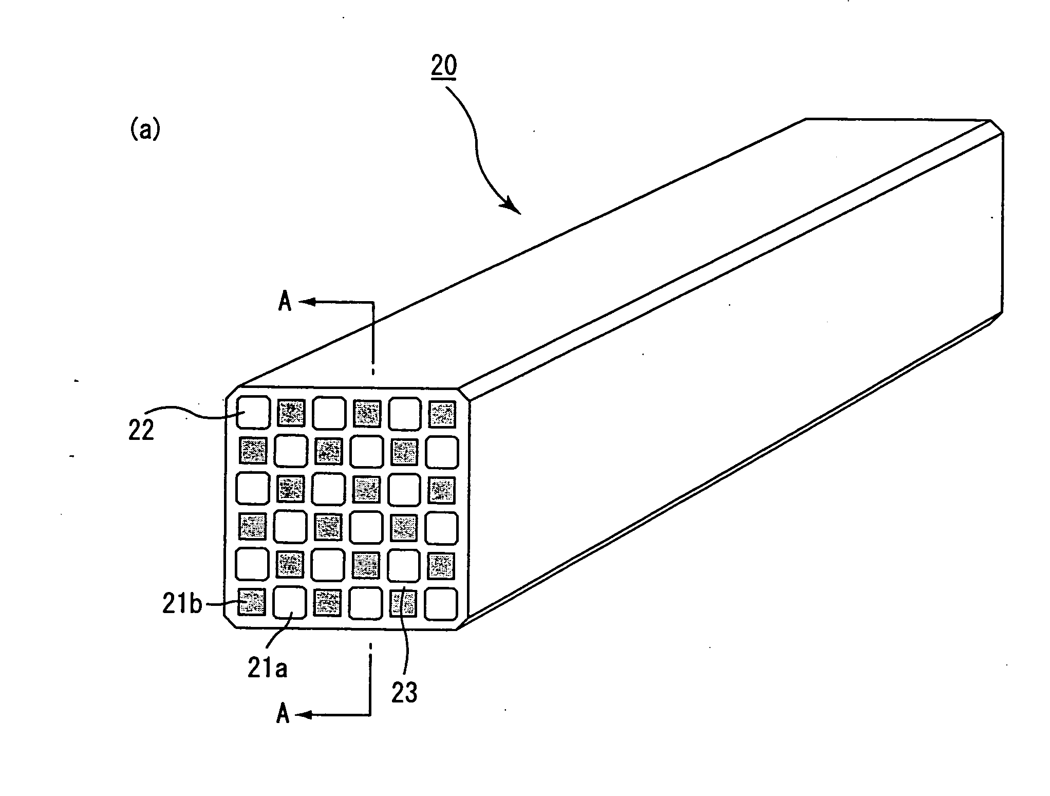
[0200] (1) Powder of α-type silicon carbide having an average particle size of 11 μm (60% by weight) and powder of β-type silicon carbide having an average particle size of 0.5 μm (40% by weight) were wet-mixed, and to loop arts by weight of the resulting mixture were added and kneaded 5 parts by weight of an organic binder (methyl cellulose) and 10 parts by weight of water to obtain a mixed composition. Next, after a slight amount of a plasticizer and a lubricant have been added and kneaded therein, the resulting mixture was extrusion-molded, so that a raw molded body, which had an octagonal cross-sectional shape in the large-capacity through hole and an quadrangle cross-sectional shape (substantially square shape) in the small-capacity through hole, with β (aperture ratio) after the sintering process being set to 1.50, was manufactured as shown in FIGS. 6(a) to 6(d).

[0201] Next, the above-mentioned raw molded body was dried by using a micro-wave drier or the like to form a cerami...


PUM

PropertyMeasurementUnit
porosityaaaaaaaaaa
porosityaaaaaaaaaa
porosityaaaaaaaaaa

Abstract

An object of the present invention is to provide a filter that makes it possible to suppress the initial pressure loss and, also, to reduce the rising rate of the pressure loss that increases as particulates accumulate; therefore, the pressure loss at the time when a prescribed amount of particulates have been collected becomes lower, and the pressure loss from the viewpoint of the period up to the recovery as a whole also becomes lower. The present invention provides a filter, which is a column shaped filter having a honeycomb structure, including a number of through holes that are placed in parallel with one another in the length direction with wall portion interposed therebetween, wherein the through holes are constituted by two types of through holes, that is, large-capacity through holes having a relatively larger cross-sectional area in the cross section perpendicular to the length direction and small-capacity through holes having a relatively smaller cross-sectional area in the cross section, with the numbers of the two types of through holes being substantially set to the same, the large-capacity through holes are sealed at one end of the filter, while the small-capacity through holes are sealed at the other end of the filter, and supposing that the ratio (a / b) of the total (a) of lengths of wall portion which is shared by one large-capacity through hole and the adjacent large-capacity through hole in the cross section perpendicular to the length direction and the total (b) of lengths of wall portion which is shared by one large-capacity through hole and the adjacent small-capacity through hole in the cross section perpendicular to the length direction is defined as a and that the ratio (A / B) of the area (A) of the cross section of the large-capacity through hole and the area (B) of the cross section of the small-capacity through hole is defined as β, α and β satisfy the relationship represented by the following formula (1): β≧(20 / 9) α2+1 (where 0<α≦1.5 and 1<β≧6)  (1).

Description

CROSS REFERENCE TO RELATED APPLICATION [0001] This application claims benefit of priority to Japanese patent applications Nos. 2002-267819 filed on Sep. 13, 2002 and 2003-57631 filed on Mar. 4, 2003, the contents of which are incorporated by reference herein. TECHNICAL FIELD [0002] The present invention relates to a filter used for removing particulates and the like contained in exhaust gases discharged from an internal combustion engine such as a diesel engine and the like. BACKGROUND ART [0003] In recent years, particulates, contained in exhaust gases discharged from internal combustion engines of vehicles such as buses, trucks, construction machines and the like, have raised serious problems as contaminants harmful to the environment and the human body. [0004] For this reason, there have been proposed various ceramics filters which allow exhaust gases to pass through porous ceramics to collect particulates in the exhaust gases, so that the exhaust gases can be purified. [0005] Co...

Claims


Application Information

Patent Timeline
Patent Type & Authority Applications(United States)
IPC IPC(8): B01D46/00B01D46/24B01D46/42F01N3/022F01N3/023F01N3/027F01N3/28
CPCB01D46/0063Y10S55/10B01D46/2451B01D46/2459B01D46/247B01D46/2474B01D46/4263B01D2046/2477B01D2046/2481B01D2046/2485B01D2046/2496F01N3/0222F01N3/023F01N3/027F01N3/2828F01N2330/06F01N2330/30F01N2330/34F01N2330/48F01N2450/28Y10S55/30B01D46/2425B01D46/249B01D46/2498B01D46/84B01D46/2484B01D46/2478B01D46/2486
Inventor HONG, SUNGTAEKOMORI, TERUOOHNO, KAZUHIGE
Owner IBIDEN CO LTD
Why Eureka
Try Eureka