Solar heat absorber panels

a technology of solar energy and absorber panels, which is applied in the direction of solar heat collectors with working fluids, solar heat collectors for particular environments, solar heat collectors, etc., can solve the problems of difficult to fit in the form of an array, and achieve the effect of reducing heat loss, facilitating connections, and being easy to achiev

Inactive Publication Date: 2005-01-27
BROATCH PETER MARTIN
View PDF5 Cites 31 Cited by
  • Summary
  • Abstract
  • Description
  • Claims
  • Application Information

AI Technical Summary

Benefits of technology

[0009] The means of connection of the panels is important, as connections need to be reliable and easy to achieve while working on a roof. This invention provides for this by having duct terminals at the edges of the panels, positioned so that when two panels are placed adjacent to each other the terminals line up and thus may be connected with a suitable connector. An advantageous method is to use a normal push fit pipe connector which may be fitted to one terminal, the other terminal then being pushed into it. If the panels are arranged in a horizontal row, with the terminals on the ends of the panels and on an axis parallel to the row, then making the connections is facilitated by being able to slide one panel along the battens towards another panel, whereupo

Problems solved by technology

Conventional flat plate panels have the disadvantage in that they normally lie over the r

Method used


Image

  • Solar heat absorber panels
  • Solar heat absorber panels
  • Solar heat absorber panels

Examples


Embodiment Construction

[0015] The invention will now be described, by way of example only, with reference to the accompanying drawings.

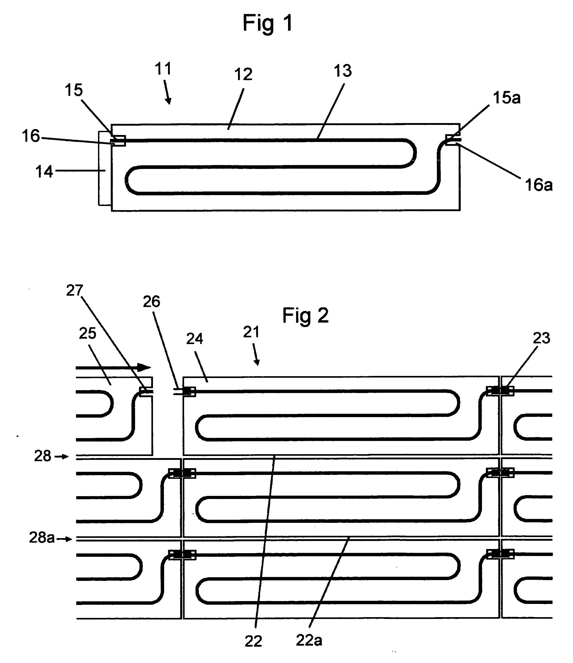
[0016] Referring first to FIG. 1, an absorber panel 11 is made of an aluminium sheet 12 coated in a coating absorptive to solar radiation, to which is welded a copper pipe 13. The pipe 13 traverses the sheet in a serpentine manner, and both ends are terminated at the edge as terminals 15 and 15a. The panel is cut away 16, 16a to allow space for connectors (not shown). An insulation board 14 is attached to the rear of the panel and protrudes at one end so that it underlies the gap between this panel and a second panel placed adjacent to it, so as to provide a barrier to light passing through the gap between the panels.

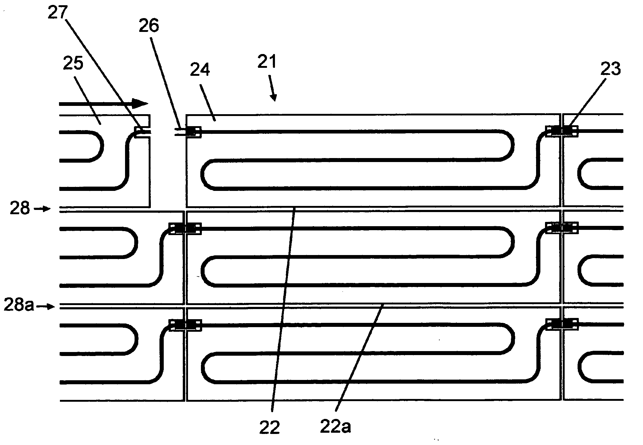
[0017]FIG. 2 shows an array of panels 21 formed of a number of horizontal rows of panels (three rows are shown). The panels are supported by horizontal battens (not shown) along the lines of the panel edges 28, 28a. Note the gaps 22, 22a between the panels w...


PUM


Abstract

An array of panels absorptive to solar radiation 21 is made up of individual panels 24, 25 etc. A duct runs along a panel 25 and terminates near the edge of the panel as a terminals 27. This terminal is positioned so that it shares a common axis with a second terminal on a second panel 24, whereby the terminals may be brought into close proximity and connected with a connector 26. This connection may be made by sliding one panel along the axis of its terminal towards a second panel.

Description

[0001] This applications claims priority from UK patent application number 0314232 filed on Jun. 19, 2003. BACKGROUND OF THE INVENTION [0002] Many different kinds of solar heat exchange panels are known. Conventional flat plate panels have the disadvantage in that they normally lie over the roof covering, and are thus visually obtrusive and not easy to fit in the form of an array. [0003] My international patent application PCT / GB01 / 04440 describes panels which are integrated into a roof or wall covering and linked by a fluid duct. This application discloses some advantageous improvements which may be made to the system, and in particular to the method of connecting absorber panels together. SUMMARY OF THE INVENTION [0004] This invention concerns heat exchange panels of the type used for absorbing solar radiation and using it to heat water. More specifically it concerns that type of panel designed to be fitted as an array to a wall or roof face. [0005] Thus according to the invention...

Claims


Application Information

Patent Timeline
IPC IPC(8): E04D13/18F24J2/04F24J2/46F24S10/75
CPCF24J2/045F24J2/268Y02E10/44F24J2002/0038Y02B10/20F24J2/4647F24S10/755F24S20/67F24S80/30F24S2020/10Y02A30/60
Inventor BROATCH, PETER MARTIN
Owner BROATCH PETER MARTIN
Why Eureka
Try Eureka