Heat exchanger

a technology of heat exchanger and heat exchanger body, which is applied in the direction of heat exchange apparatus safety devices, lighting and heating equipment, and stationary conduit assemblies, etc., can solve the problems of large downtime of the apparatus with which the heat exchanger is used, the difficulty of assembly of the heat exchanger from its individual parts, and the difficulty of pre-assembly fastening type, etc., to achieve the effect of convenient manufactur

Inactive Publication Date: 2005-01-27
MODINE MFG CO
View PDF1 Cites 21 Cited by
  • Summary
  • Abstract
  • Description
  • Claims
  • Application Information

AI Technical Summary

Benefits of technology

[0009] It is the principal object of the invention to provide a new and improved heat exchanger. More specifically, one object of the invention is to provide a heat exchanger that may be readily manufactured with little or no use of jigs or fixtures in the pre-assembly process.

Problems solved by technology

A typical problem that occurs in the production of such heat exchangers is that the heat exchanger must be assembled from its individual parts in preparation for brazing or soldering.
This type of pre-assembly fastening is problematical in the fabrication of heat exchangers because of the required slit.
In addition, so-called “thermal cycling” that occurs during the operation of heat exchangers, often leads to breaks.
Temperature gradients also lead to the same problem.
Of course, if the thermal stress leads to cracks at tube to header joints, the heat exchanger begins to leak and frequently will require some sort of repair which can be expensive and which can lead to extensive down time for the apparatus with which the heat exchanger is used.

Method used


Image

  • Heat exchanger
  • Heat exchanger
  • Heat exchanger

Examples


Embodiment Construction

[0034] As alluded to previously, the heat exchanger of the present invention is ideally suited for vehicular use as, for example, a vehicular radiator or charge air cooler. However, no limitation to vehicular use, or to a radiator, or charge air cooler is intended because those skilled in the art will recognize that the heat exchanger of the invention may be used in a variety of environments and for a variety of purposes. For example, the same could be utilized in a heating system for a building, or the like. In any event, no limitation to a particular environment of use or to a particular use is intended except insofar as expressly stated in the appended claims.

[0035] With the foregoing in mind, several embodiments of the invention will now be described.

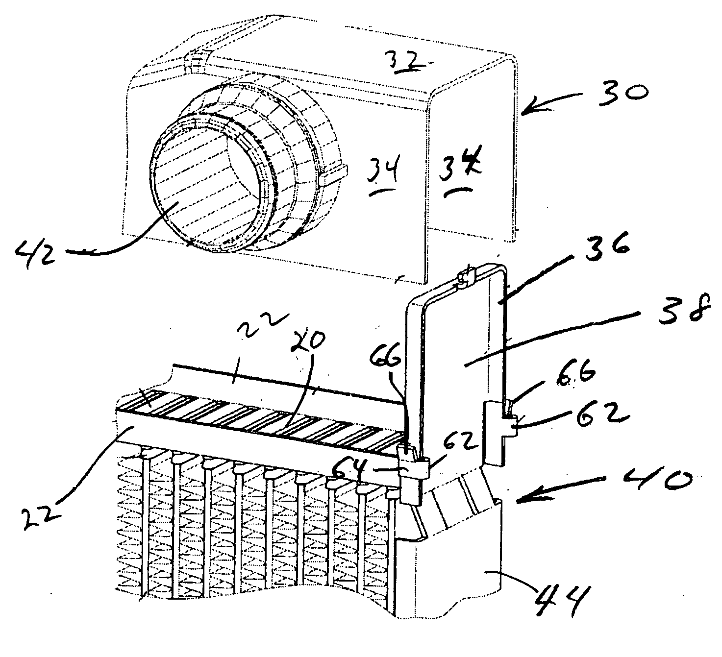
[0036] Turning first to FIGS. 8, 9, and 10, a typical heat exchanger embodying the invention is shown fragmentarily. The same includes two, spaced, parallel header plates 20 (only one of which is shown) having upturned side edges ...


PUM


Abstract

An improved heat exchanger includes an integral side piece/end cap structure for closing the ends of tanks and providing a side piece for each side of the heat exchanger and includes connecting strands between an end cap section and a side piece section that are weak, allowing the breakage thereof prior to excessive thermal stresses being placed on tube to the header joints. Also disclosed is the use of clips on end cap section and/or tank ends together with a tab on the end cap section which may be used to self-fixture of the components during assembly.

Description

FIELD OF THE INVENTION [0001] This invention relates to a heat exchanger, and more particularly, to a heat exchanger whose components are assembled to one another by soldering or brazing, for example, aluminum heat exchangers. BACKGROUND OF THE INVENTION [0002] Heat exchangers for vehicles as, for example, radiators or charge air coolers, conventionally include a plurality of parallel, spaced, flat tubes that extend between header plates with tube slots which sealingly receive the ends of the flat tubes. Serpentine fins are disposed between adjacent ones of the tubes and collecting tanks are assembled in sealed relation to header plates on sides thereof opposite the tubes. As is typical with the heat exchangers utilizing the serpentine fins, to facilitate assembly, side pieces are located along each side of the heat exchanger core and extend between corresponding ends of the two headers to sandwich a serpentine fin against an endmost tube in the core. Frequently, the heat exchangers...

Claims


Application Information

Patent Timeline
Patent Type & Authority Applications(United States)
IPC IPC(8): F28F9/00F28F9/02
CPCF28F9/001F28F2265/26F28F2220/00F28F9/0202
Inventor LAMICH, BERHNHARDBROST, VIKTOR
Owner MODINE MFG CO
Why Eureka
Try Eureka