Medial instrument holding and presentation system

a technology of applied in the field of medial instrument holding and presentation system, can solve the problems of not taking into account, wasting sterilizer and shelf space, and the container may be too large to fit in the small sterilizer found in some physician offices and clinics, etc., and achieves the effect of easy grasping, easy and inexpensive quantity production, and reducing space taken

Inactive Publication Date: 2005-01-27
SYMMETRY MEDICAL USA
View PDF18 Cites 23 Cited by
  • Summary
  • Abstract
  • Description
  • Claims
  • Application Information

AI Technical Summary

Benefits of technology

[0021] Thus, it will be appreciated that while the holder modules are packed tightly together within the outer case in order to minimize the space taken up by that assembly in the sterilizer or on the shelf, the modules may be spread out over the larger area surface of the presentation tray so that the instruments therein may be grasped easily by the surgeon.
[0022] All of the components of my system may be simple, unitary, molded plastic parts which are easy and inexpensive to make in quantity and which do not require initial assembly or subsequent disassembly for cleaning purposes.

Problems solved by technology

While that assembly is satisfactory in many respects, it is disadvantaged in that it does not take into account the fact that the numbers of instruments in the sets required for different procedures may vary over a wide range.
This means that if the container is used to sterilize and store a small set of instruments, the container would be mostly empty and thus waste sterilizer and shelf space.
Likewise, that container may be too large to fit in the small sterilizers found in some physician offices and clinics.
Another disadvantage of that patented container is that the grommets which support the instruments must be removed from the internal tray following surgery because blood and tissue collect in the spaces between the grommets and the tray.
This adds to the cost of cleaning and maintaining that container assembly.

Method used


Image

  • Medial instrument holding and presentation system
  • Medial instrument holding and presentation system
  • Medial instrument holding and presentation system

Examples


Embodiment Construction

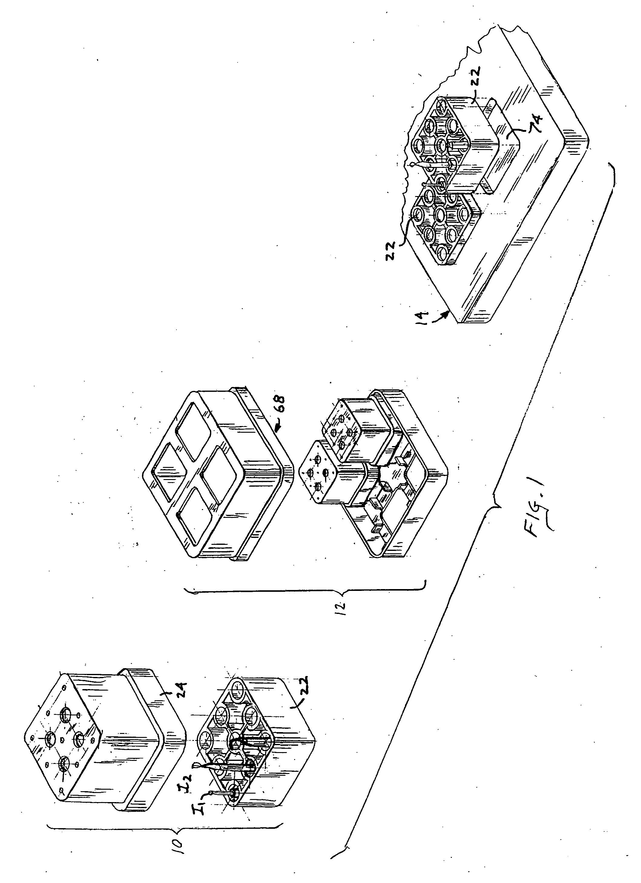
[0033] Referring to FIG. 1 of the drawings, my system or assembly comprises three main components, namely one or more instrument holder modules shown generally at 10, an outer sterilization / storage case shown generally at 12 for containing modules 10 during sterilization and storage, and a presentation tray shown generally at 14 for supporting the modules in an orderly manner so that the instruments therein are readily accessible to a surgeon who will use those instruments in order to perform a particular operation. Preferably, all of the system components are made of a suitable rigid plastic material able to withstand sterilization, e.g. polyphenylsulfone.

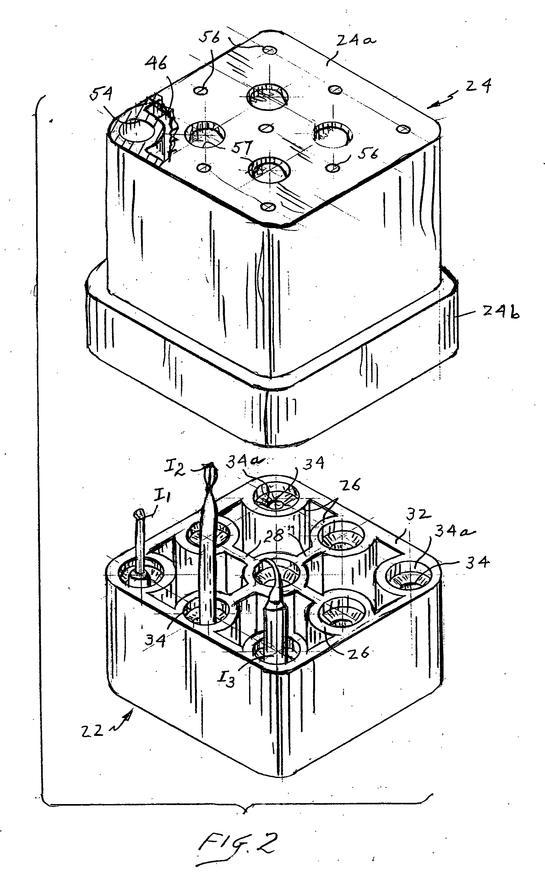
[0034] As shown in FIGS. 2 and 3A, each module 10 includes a base 22 and a cover 24 that may be removably engaged over the base. Base 22 is preferably a unitary molded plastic part formed with a plurality of vertical tubes 26 some of which may be interconnected by webs 28 and all of which are surrounded by a peripheral web or wal...


PUM

PropertyMeasurementUnit
areaaaaaaaaaaa
sizeaaaaaaaaaa
lengthaaaaaaaaaa

Abstract

A medical instrument holder assembly comprises a holder module base including first tubes defining first passages, each first passage having open upper and lower ends, at least one first web connecting and supporting those first tubes in parallel spaced-apart relation so that a fluid can circulate around and between the first tubes, and instrument supports underlying the first tubes for supporting medical instruments placed in the first passages while allowing a fluid to circulate through those passages. The holder assembly also includes a cover for seating on the base and covering the instruments supported thereby, the cover being formed by second tubes defining second instrument receiving passages, each second passage having upper and lower open ends, the lower ends having the same cross-sections as the upper ends of the first passages. At least one second web connects and supports the second tubes in parallel spaced-apart relation so that when the cover is seated on the base, the corresponding first and second passages are co-linear. Preferably, the assembly also includes an outer sterilization/storage case for containing a plurality of covered holder module bases packed closely together and a presentation tray capable of supporting a plurality of the holder module bases so that the instruments therein can be grasped easily by a surgeon.

Description

CROSS-REFERENCE TO RELATED APPLICATION [0001] This application claims the benefit of Provisional Application No. 60 / 488,892, filed on Jul. 21, 2003.BACKGROUND OF THE INVENTION [0002] 1. Field of the Invention [0003] This invention relates to a system or assembly for holding selected sets of medical instruments or tools during sterilization and storage prior to use and for presenting them in a logical order when they are being used to perform a particular surgical procedure. [0004] Different surgical procedures require the use of different sets of instruments or tools, the number of tools in the set depending upon the complexity of the procedure. For example, for a tooth implant, the instrument or tool set may include a twist drill, a drill extension, a driver, and various size screws. Sometimes the set includes duplicate tools in the event one breaks. If more than one implant is involved in the procedure, more and / or different tools may be required than for a single implant. Thus pr...

Claims


Application Information

Patent Timeline
Patent Type & Authority Applications(United States)
IPC IPC(8): A61B19/02A61C3/04A61L2/07A61L2/26
CPCA61B19/0256A61B19/026A61B19/0271A61B2019/0278A61L2202/24A61C3/04A61L2/07A61L2/26A61L2202/182A61B2019/0279A61B50/20A61B50/30A61B50/33A61B2050/3008A61B2050/3009
Inventor RILEY, EDWARD D.
Owner SYMMETRY MEDICAL USA
Why Eureka
Try Eureka