Method and apparatus for laser inscription of an image on a surface

a technology of laser inscription and surface, applied in metal working apparatus, manufacturing tools, welding/soldering/cutting articles, etc., can solve the problems of substantial maintenance problems, high cost of robotic equipment, slow manual operation, etc., and achieve the effect of shortening the light path and less maintenan

Inactive Publication Date: 2005-01-27
DEROSSETT THOMAS JR +1
View PDF6 Cites 12 Cited by
  • Summary
  • Abstract
  • Description
  • Claims
  • Application Information

AI Technical Summary

Benefits of technology

[0011] Another object of the present invention is to provide apparatus for etching surfaces which can be operated by a minimum of personnel in a safe and efficient manner.
[0012] Still another object of the invention is to shorten the light path from the laser to the surface being etched.
[0013] Yet another object of the invention is to provide apparatus for laser inscription of a surface that requires less maintenance.

Problems solved by technology

However, manual operation is slow and not suited to repetitive operations while robotic equipment is expensive and can present a substantial maintenance problem.
Most of the etchant compounds are hydrogen fluoride based and as such, are highly corrosive and dangerous to use.
Also, disposal of such materials can also be a serious problem in view of the potentially harmful environmental affect such materials may have.
Needless to say the disposal of toxic materials is an expensive operation.
Sandblasting, if not properly carried out, also posses an environmental threat as well as a potential safety hazard to the operators and other personnel in the immediate area of the sandblasting operation.
Neither chemical etching nor sandblasting readily lend themselves to automation and in most cases, the indicia which can be etched onto the glass surface are limited to non-machine readable numbers.
Moreover, poor technique, particularly in the case of chemical etching, can lead to erroneous results due to blurring of the etched image making it difficult to read, especially by machine.
It must be noted, particularly in the case of automobile VIN numbers, that accuracy and image quality are of the utmost importance and mistakes require the replacement of the vehicle window or windshield, an expensive procedure.
In addition, replacement of marking heads can be time consuming due to the necessity of assembling the new marking head and the flexible optical path and aligning the laser beam with the optical path and the marking head.

Method used


Image

  • Method and apparatus for laser inscription of an image on a surface
  • Method and apparatus for laser inscription of an image on a surface
  • Method and apparatus for laser inscription of an image on a surface

Examples


Embodiment Construction

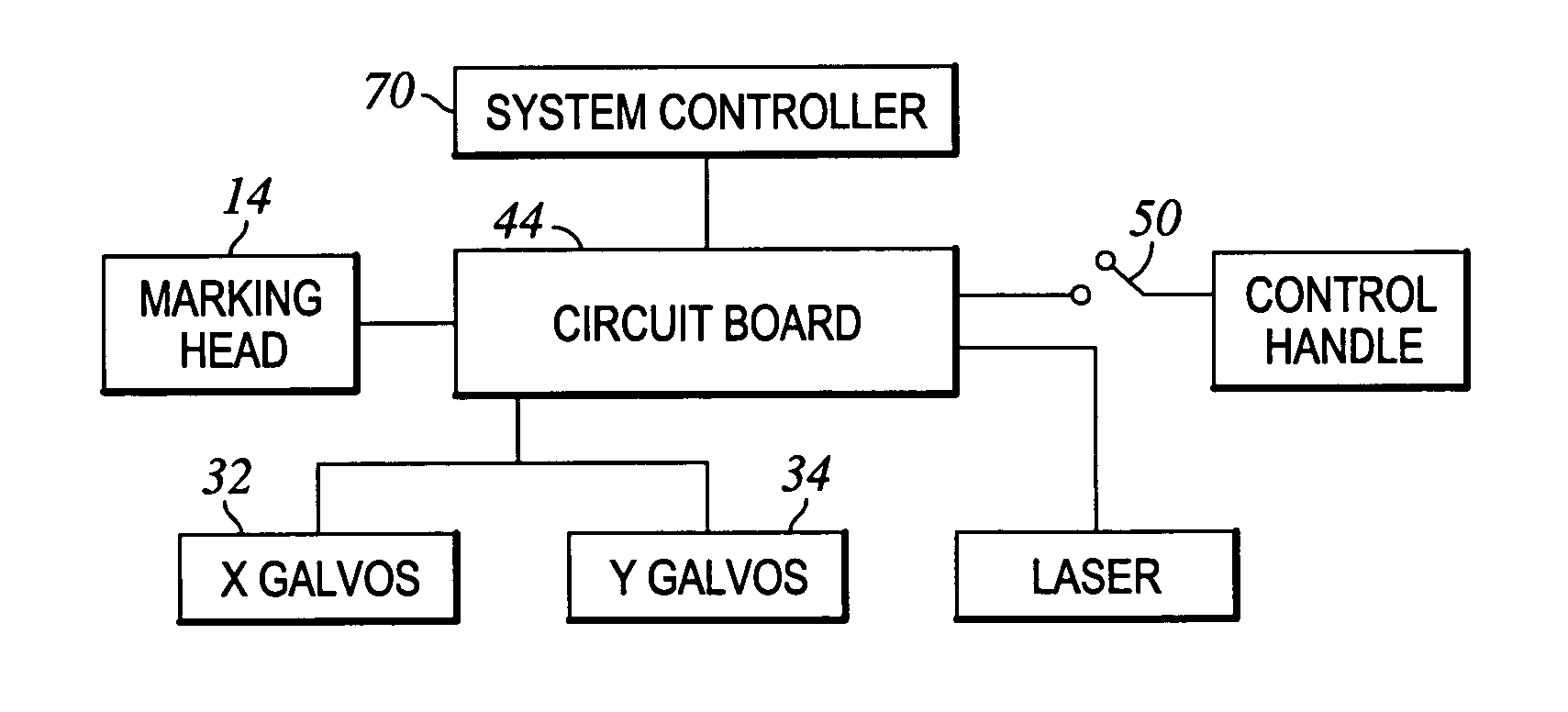
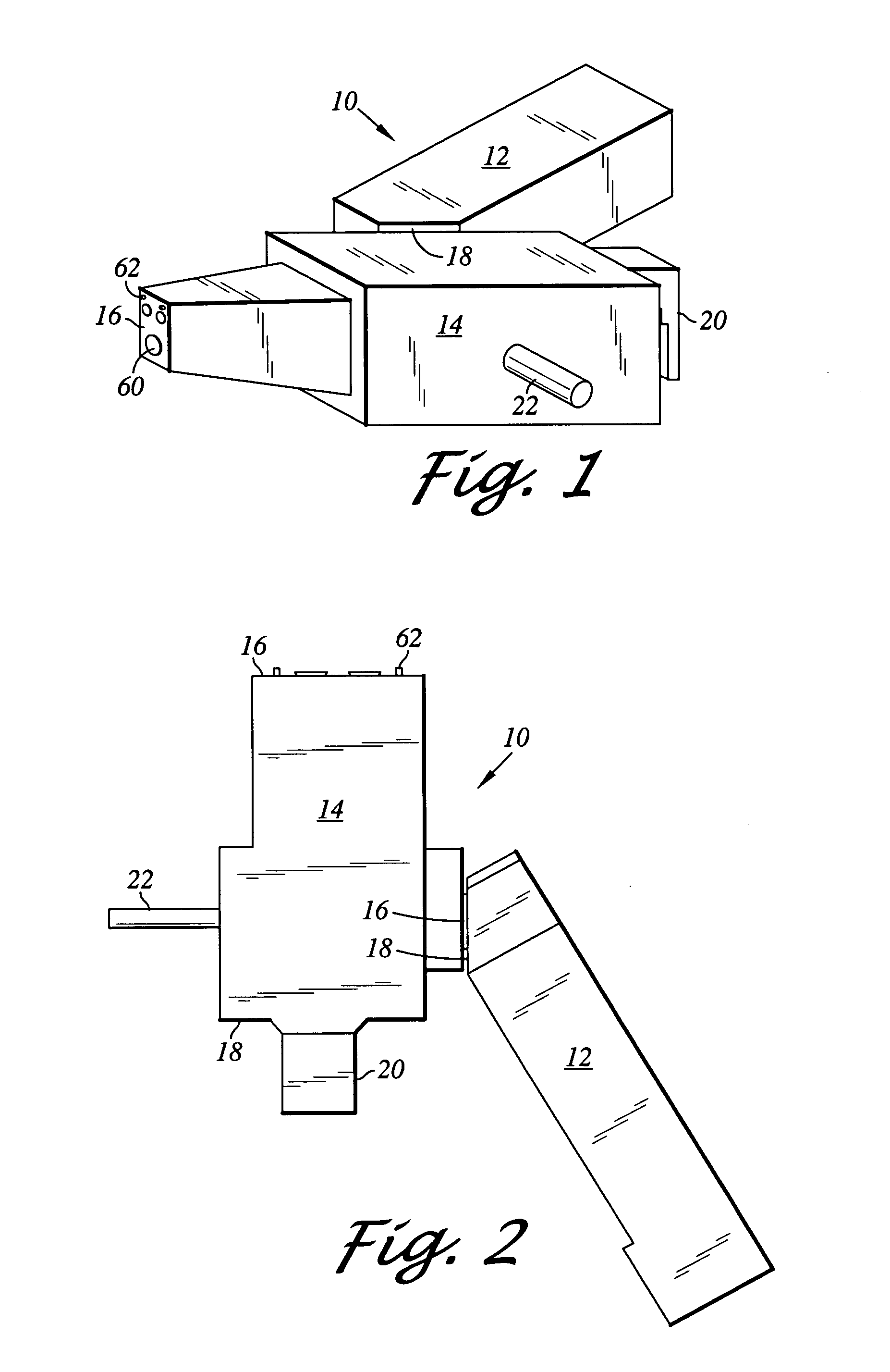
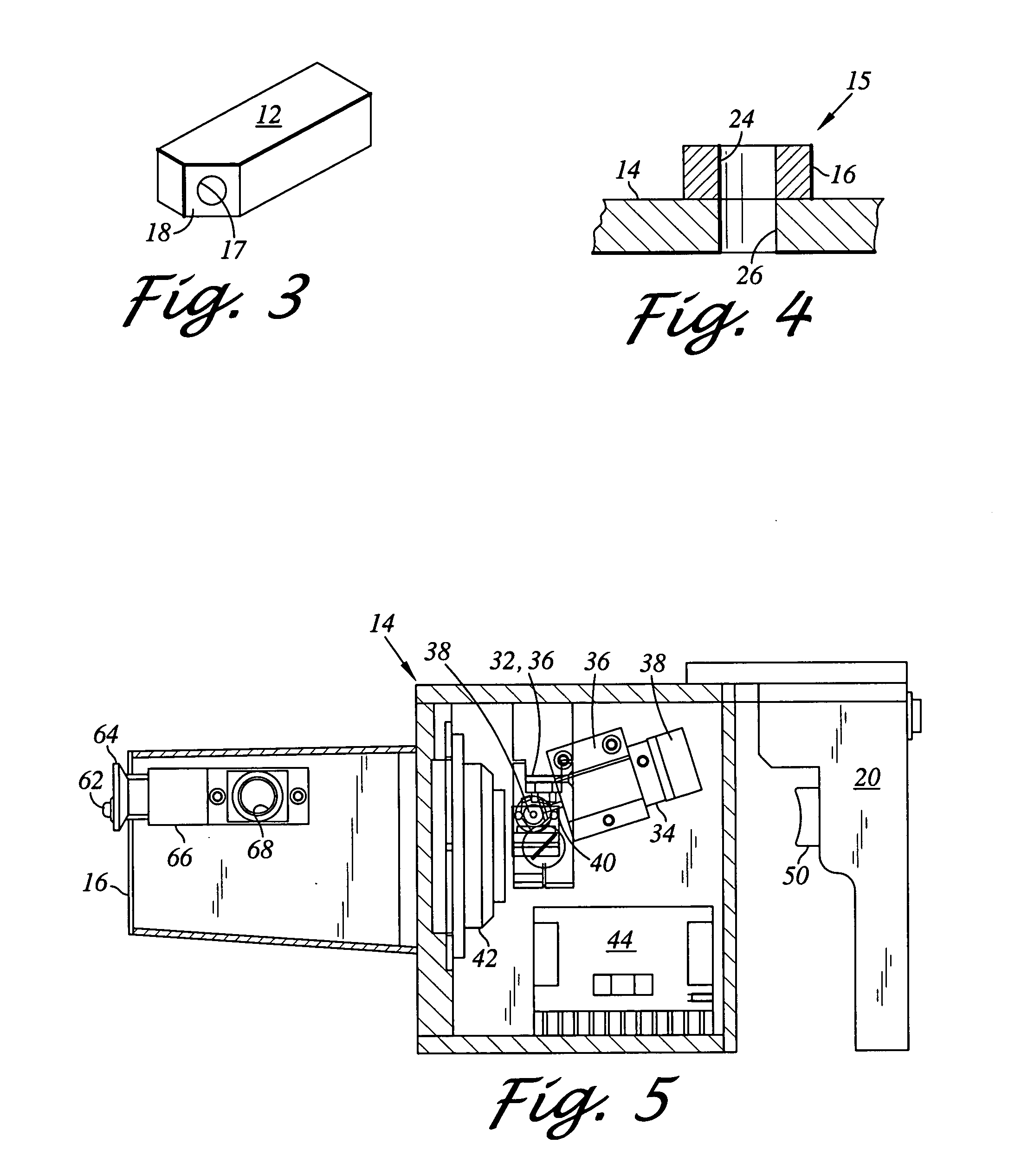
[0028] The invention is described herein in connection with the inscription of indicia on vehicle windows. The apparatus of the present invention, shown generally as 10, is illustrated in a simplified perspective view in FIG. 1 and in top plan view in FIG. 2. The apparatus 10 comprises an emitter housing 12 comprising a housing having top, bottom side and end walls. As illustrated, a marking head 14 is pivotally mounted on a side wall of the emitter housing. A laser source of conventional design that is capable of emitting a beam to which the surface being etched is not transparent and the associated electronics in support thereof are disposed in the emitter housing 12. The laser and associated electronics are connected to a suitable power source (not shown). An eximer or CO2 laser is preferred for use in the present invention because the emission of these lasers is particularly suited for etching oxide containing surfaces such as glass, anodized aluminum, ceramic oxides and the lik...


PUM

PropertyMeasurementUnit
emission poweraaaaaaaaaa
energyaaaaaaaaaa

Abstract

A system for scribing indicia into a surface using a laser as an emission source. Comprises an emitter housing in which is disposed a laser source and a marking head pivotally joined to a wall of the emitter housing. Means in the marking head are provided for controlling the beam scan over the surface being inscribed responsive to a digitized control signal representing the indicia. In a preferred embodiment the marking head is pivotally attached to a side wall of the emitter housing that has been configured to define a mounting face.

Description

FIELD OF THE INVENTION [0001] The invention relates to the inscription of images on a surface and more particularly to a method and apparatus for creating permanent images on glass and other inorganic oxide containing surfaces using high energy light. BACKGROUND OF THE INVENTION [0002] The inscription of images on various surfaces has become increasingly important in recent years for the permanent identification of valuable objects in addition to forming decorative designs on surfaces. For example, for the permanent identification of automobiles, trucks and the like, vehicle VIN Numbers or other identifying indicia are permanently inscribed on the windows of the vehicle at various locations to provide a non-removable identification for the vehicle. Many insurance companies offer a discount from the cost of insuring the vehicle if such permanent indicia are placed on the vehicle. Such indicia, for example a bar code, can also provide an access code for the retrieval of the history of...

Claims


Application Information

Patent Timeline
Patent Type & Authority Applications(United States)
IPC IPC(8): B23K26/08B23K26/14C03C23/00
CPCC03C23/0025B23K26/08B23K2201/007B23K26/1441B23K26/1494B23K26/0884B23K26/1436B23K2101/007
Inventor DEROSSETT, THOMAS JR.MILLER, TIMOTHY
Owner DEROSSETT THOMAS JR
Why Eureka
Try Eureka