Switch mechanism

a switch mechanism and mechanism technology, applied in the direction of contact mechanisms, shock absorbers, mechanical devices, etc., can solve the problem that the switch mechanism is not readily assembled, and achieve the effect of damped

Inactive Publication Date: 2005-01-27
SIEMENS AG
View PDF3 Cites 6 Cited by
  • Summary
  • Abstract
  • Description
  • Claims
  • Application Information

AI Technical Summary

Benefits of technology

[0008] In the embodiment of such an arrangement of the damping element, it is ensured that the piston is immersed in the hydraulic fluid and consequently preserves its damping characteristic. Independently of a vertical or horizontal assembly position of the switch mechanism on the switch, the position of the damping element is maintained. Consequently, the switch mechanism can be used universally. The slight swinging about the angular position of 45° makes it possible for movements which proceed on a circular path to be effectively damped. Such an arrangement allows a low-cost, reliable hydraulic damping element to be used in the switch mechanism.

Problems solved by technology

On account of the alignment of the damping elements, it is not readily possible for the switch mechanism to be assembled on the switch in different positions.

Method used


Image

  • Switch mechanism
  • Switch mechanism
  • Switch mechanism

Examples


Embodiment Construction

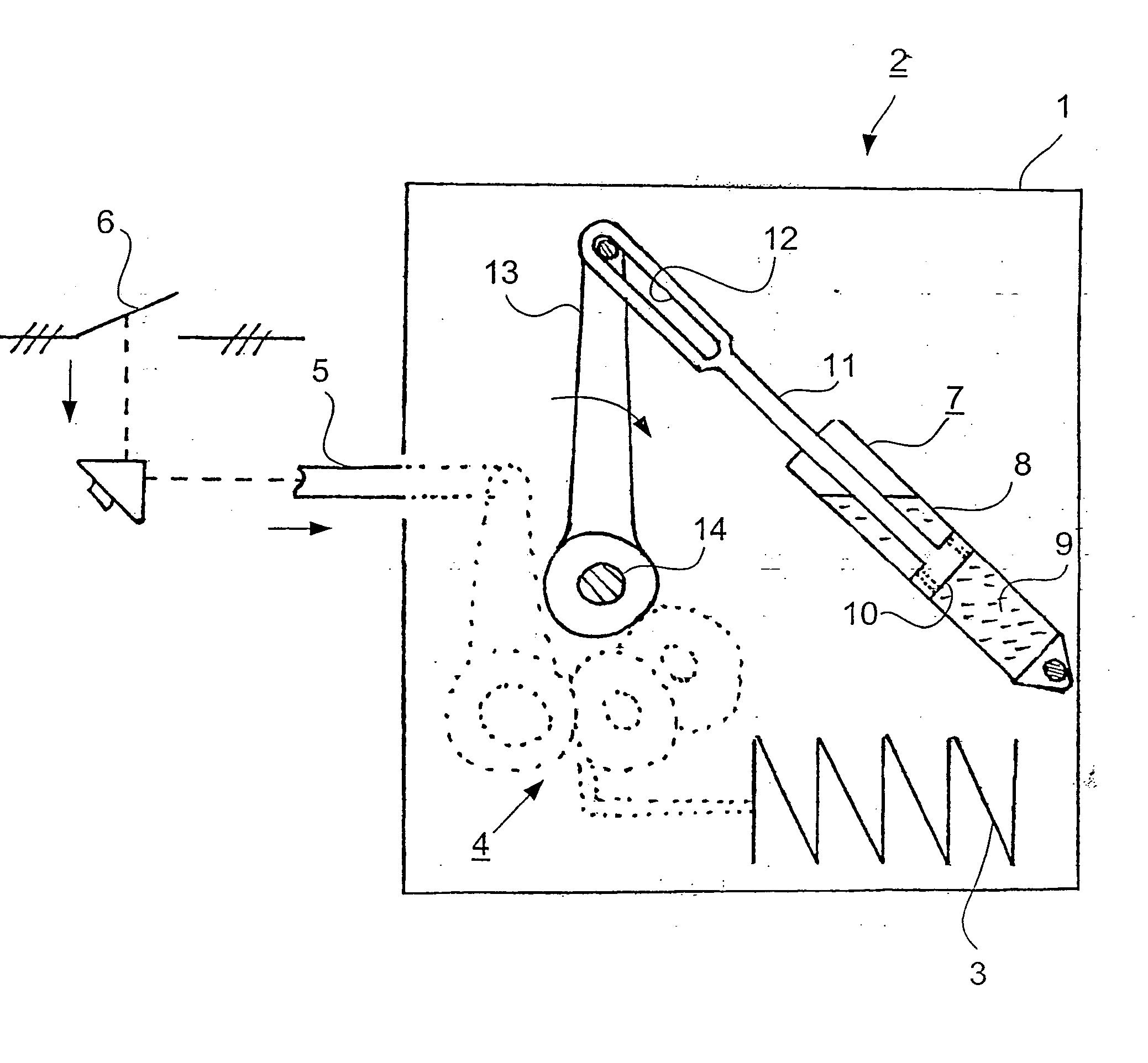
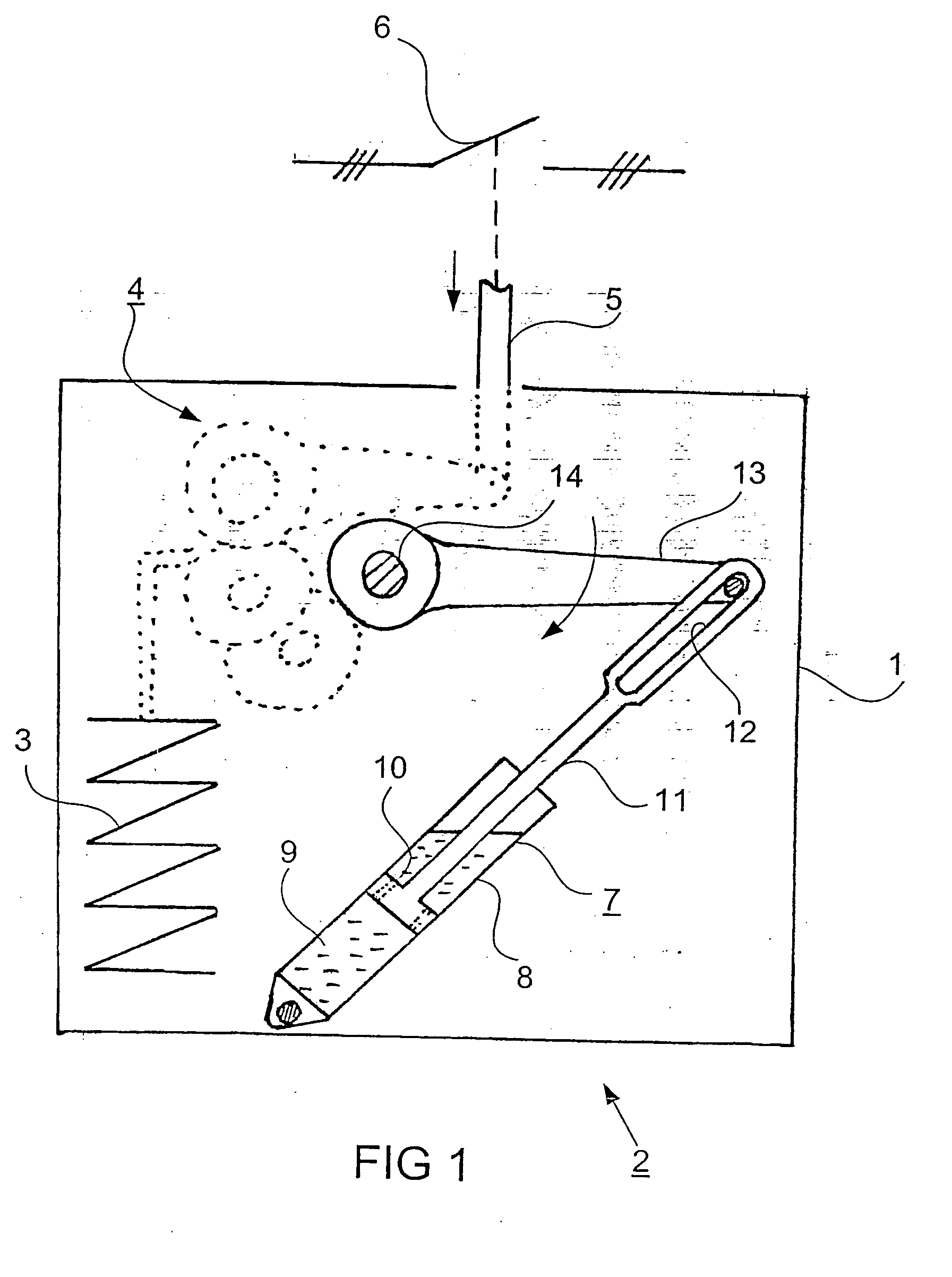
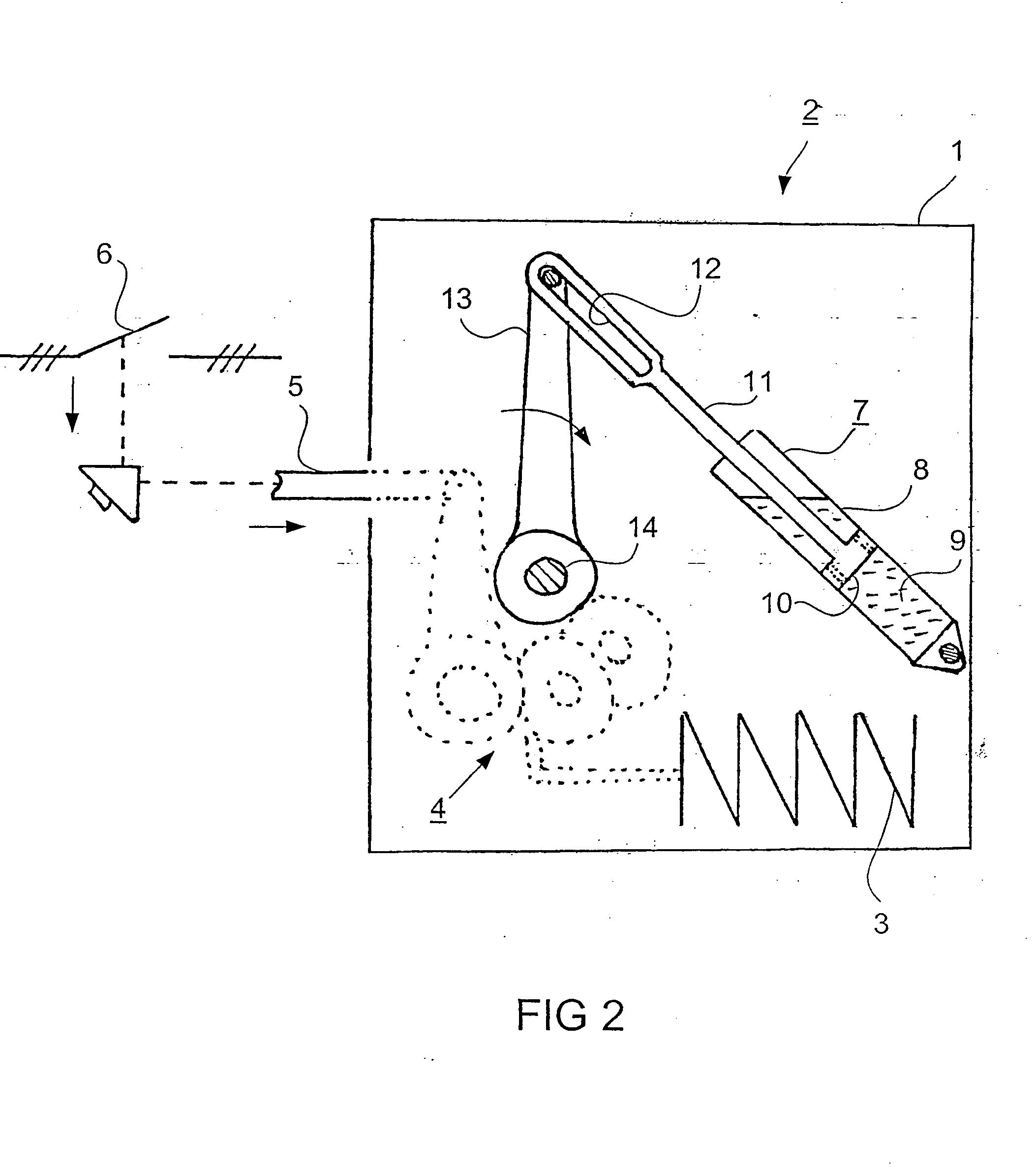
[0012]FIG. 1 shows a housing 1 of a stored-energy spring mechanism 2. The stored-energy spring mechanism 2 has a spring 3 for providing the operating energy. The spring 3 can be stressed by an electric motor (not represented). The spring 3 acts on a gear mechanism 4, which is indicated in the FIG. 1 by dashed lines. The gear mechanism 4 transmits the energy provided by the spring 3 to a drive rod 5, which drives the switching poles 6 of an electrical switching device. A damping element 7 is provided for damping the abruptly occurring switching movements. The damping element 7 is swung out from the vertical by an angle of about 45° and has a cylinder 8 which is filled with hydraulic fluid 9 and in which a piston 10 moves. The damping element 7 is arranged pivotably on the housing 1. The piston 10 is designed such that, in the event of great relative speeds of the piston 10 and cylinder 8, it moves with high resistance within the hydraulic fluid 9. To accomplish this movement characte...


PUM


Abstract

The aim of the invention is to be able to arrange a switch mechanism comprising a hydraulic damping element (7) in two different assembly positions on a switch. To this end, the hydraulic damping element (7) must demonstrate a full functional capacity in both assembly positions. In order to ensure the same functional capacity in a first, for example, vertical assembly position and in a second, for example, horizontal assembly position, the damping element (7) is arranged in a position which deviates by 45° from the vertical.

Description

CLAIM FOR PRIORITY [0001] This is a national stage of PCT / DE01 / 03877 filed 4 Oct. 2001 which is based on German application 10061164.8 filed 30 Nov. 2000.TECHNICAL FIELD OF THE INVENTION [0002] The invention relates to a switch mechanism with a pivotably mounted, gravity-opposing hydraulic damping element for damping a switching movement. BACKGROUND OF THE INVENTION [0003] A switch mechanism of this type is known for example from the brochure “SF6 circuit breaker HPL” of the Asea company, June 1986. In it, a switch mechanism is schematically represented on page B05-A:23. The switch mechanism represented is a stored-energy spring mechanism. The necessary operating energy is provided by the relaxation of previously stressed spring assemblies. The operating energy is transmitted via a gear mechanism, which has gear wheels, shafts and levers. [0004] To damp the high forces abruptly occurring in a switching operation, damping elements which absorb excess energy when an end position of th...

Claims


Application Information

Patent Timeline
Patent Type & Authority Applications(United States)
IPC IPC(8): F16F9/40F16F9/54H01H3/60
CPCF16F9/54H01H3/605F16F2230/28
Inventor LOEBNER, FRIEDRICHLUTZKE, GUNNAR
Owner SIEMENS AG
Why Eureka
Try Eureka