Microwave oven

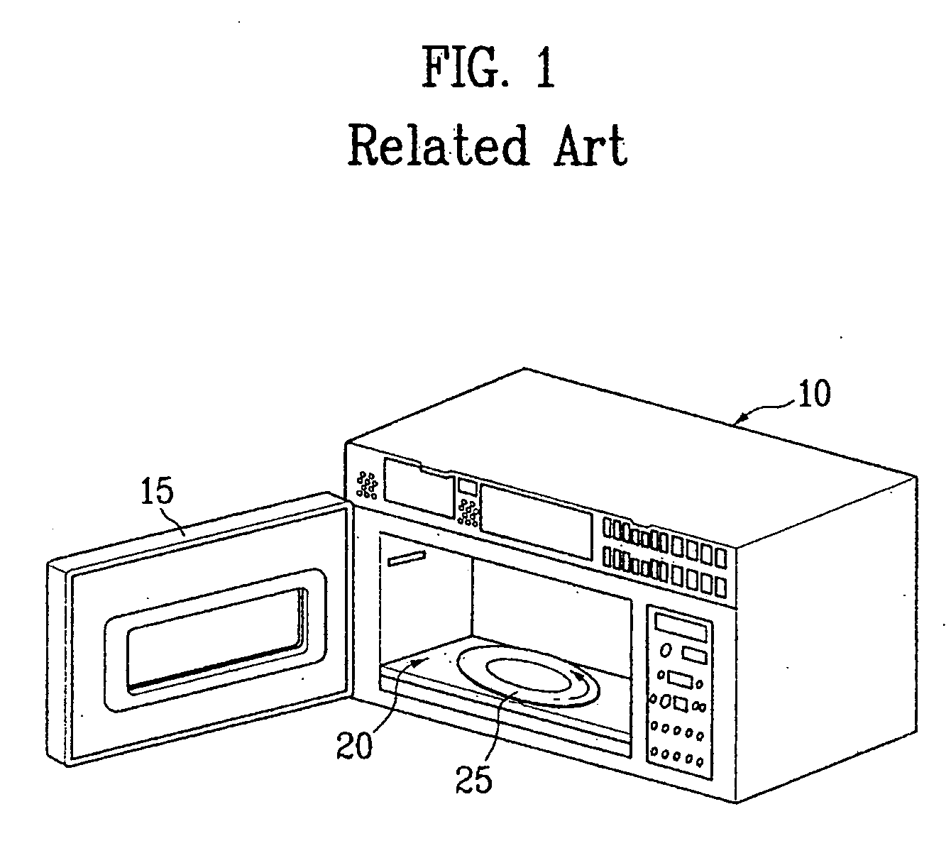
a microwave oven and microwave technology, applied in the field of microwave ovens, can solve the problems of inefficiency, inability to use the inside space of the microwave oven, and 25/b>has difficulty in cooking food in a long container, so as to achieve the effect of improving structure and easy cooking of long food

Inactive Publication Date: 2005-01-27
DOTCOMMENTS COM INC +1
View PDF10 Cites 17 Cited by
  • Summary
  • Abstract
  • Description
  • Claims
  • Application Information

AI Technical Summary

Benefits of technology

[0011] An object of the present invention is to provide a tray assembly of an improved structure which enables easy cooking of long food.
[0012] Another object of the present invention is to provide a tray assembly of an improved structure which enables uniform cooking of, not only long food, but also general food, on the whole.

Problems solved by technology

However, the microwave oven with the circular tray 25 has difficulty in cooking food in a long container.
Therefore, an inside space of the microwave oven can not be used, efficiently.

Method used


Image

  • Microwave oven
  • Microwave oven
  • Microwave oven

Examples


first embodiment

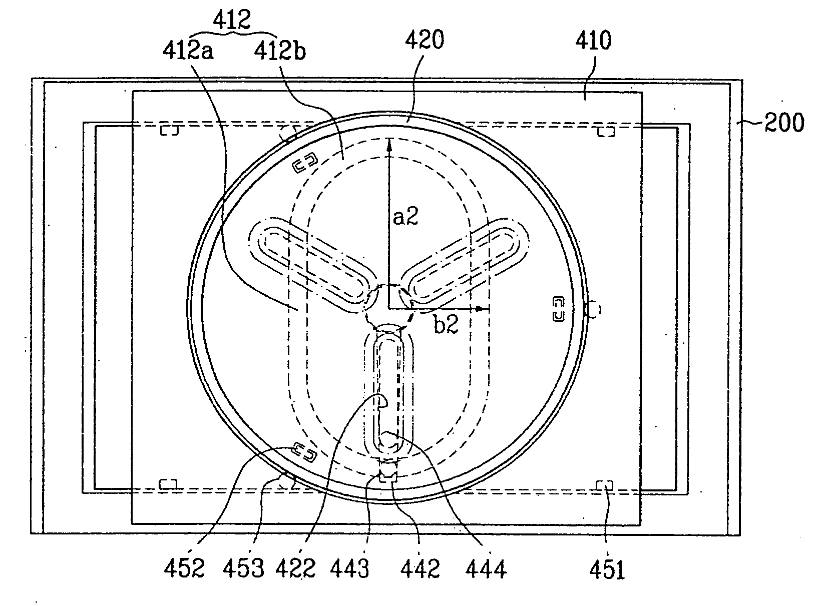
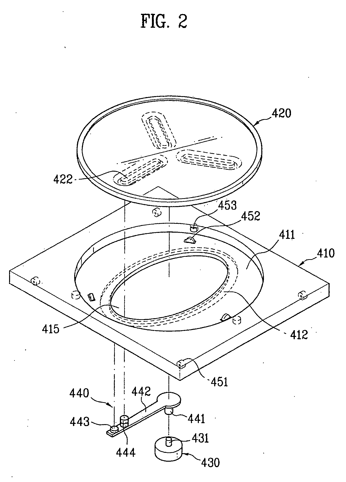
[0080] In the meantime, thus, the first tray 410 is slidably engaged with the first bushing 443 on the link 440. For this, the first tray 410 has a first receiving member provided to an underside surface of the first tray 410. In the first embodiment illustrated in FIG. 2, the first receiving member is a guide groove 412 in the underside surface of the first tray 410. The guide groove 412 has a depth, and is elliptical when seen from a surface the guide groove 412 is engaged with the first bushing 443 on the link 440.

[0081] However, in the first embodiment, the first receiving member is not limited to the guide groove 412. For example, the first receiving member may be a first ridge projected from the underside of the first tray 410. In this case, an inside wall of the first ridge engaged with the first bushing 443 has a shape the same with the guide groove 412.

[0082] The first receiving member, for an example, the guide groove 412, is provided along a circumference of the opening ...

second embodiment

[0127] According to this, the present invention suggests a second embodiment that has an improved structure for solving the foregoing problem. The tray assembly in accordance with a second preferred embodiment of the present invention is illustrated in FIG. 14, which will be described in more detail.

[0128] Referring to FIG. 14, the tray assembly in accordance with a second preferred embodiment of the present invention includes a first tray 410, a second tray 420, and a roller parts 450 for supporting an underside and circumference to the second tray 420, and enabling the second tray 420 to rotate with respect to the first tray 410 smoothly. Since structures of the first tray 410, the second tray 420, and the link 440 are similar to ones described with reference to FIG. 2, only a structure of the roller part 450 will be described.

[0129] Referring to FIG. 14, the roller parts 450 are provided to an inside wall of the receiving portion 411 of the first tray 410. It is preferable that ...

fourth embodiment

[0157] In the meantime, a second tray 420 is provided on the rotating supporter 610. The second tray 420 is circular, and, different from the first to fourth embodiment, has no second receiving portion.


PUM


Abstract

Microwave oven including a case with a door, a cooking chamber in the case openable/closable with the door, and having a microwave applicable thereto, a first tray mounted in the cooking chamber to reciprocate therein, a second tray rotatably mounted on the first tray, and a link engaged with the motor and the first tray such that the first tray reciprocates within the cooking chamber, and further engaged with the motor and the second tray such that the second tray rotates with respect to the first tray.

Description

[0001] This application claims the benefit of the Korean Application Nos. P2003-0050537 filed on Jul. 23, 2003, P2003-0051362 filed on Jul. 25, 2003, P2003-0051961 filed on Jul. 28, 2003, P2003-0052227 filed on Jul. 29, 2003, and P2003-0053465 filed on Aug. 1, 2003, and P2003-0055178 filed on Aug. 9, 2003, which are hereby incorporated by reference. BACKGROUND OF THE INVENTION [0002] 1. Field of the Invention [0003] The present invention relates to microwave ovens, and more particularly, to a tray assembly in the microwave oven, which moves a container containing food within a cooking chamber for uniform irradiation of a microwave to the food. [0004] 2. Background of the Related Art [0005] The microwave oven defrosts or heats food by using heat from friction of molecules of food caused by vibration of the molecules coming from direction of the microwave thereto. FIG. 1 illustrates a typical microwave oven, referring to which the microwave oven will be described, in more detail. [000...

Claims


Application Information

Patent Timeline
Patent Type & Authority Applications(United States)
IPC IPC(8): H05B6/80
CPCH05B6/6411
Inventor CHOI, SEONG SOO
Owner DOTCOMMENTS COM INC
Why Eureka
Try Eureka