Paper sheet storing and releasing apparatus

a technology of paper storing and releasing apparatus, which is applied in the direction of thin material handling, instruments, coin counters, etc., can solve the problems of dust infiltrating the atm, dust adhesion, and tape is liable to be easily damaged locally, so as to reduce the damage of tap

Active Publication Date: 2005-01-27
HITACHI CHANNEL SOLUTIONS CORP
View PDF5 Cites 29 Cited by
  • Summary
  • Abstract
  • Description
  • Claims
  • Application Information

AI Technical Summary

Benefits of technology

[0007] Accordingly, it is an object of the present invention to provide a paper sheet storing and releasing apparatus which can reduce damage on a tape which is attributed

Problems solved by technology

There exists a possibility that dust infiltrates into the ATM through a ventilation port or slits of the housing which are formed for lowering the temperature elevation in the inside of the housing.
Further, there exists a possibility that dust adheres to bills which a user casts into th

Method used


Image

  • Paper sheet storing and releasing apparatus
  • Paper sheet storing and releasing apparatus
  • Paper sheet storing and releasing apparatus

Examples


second embodiment

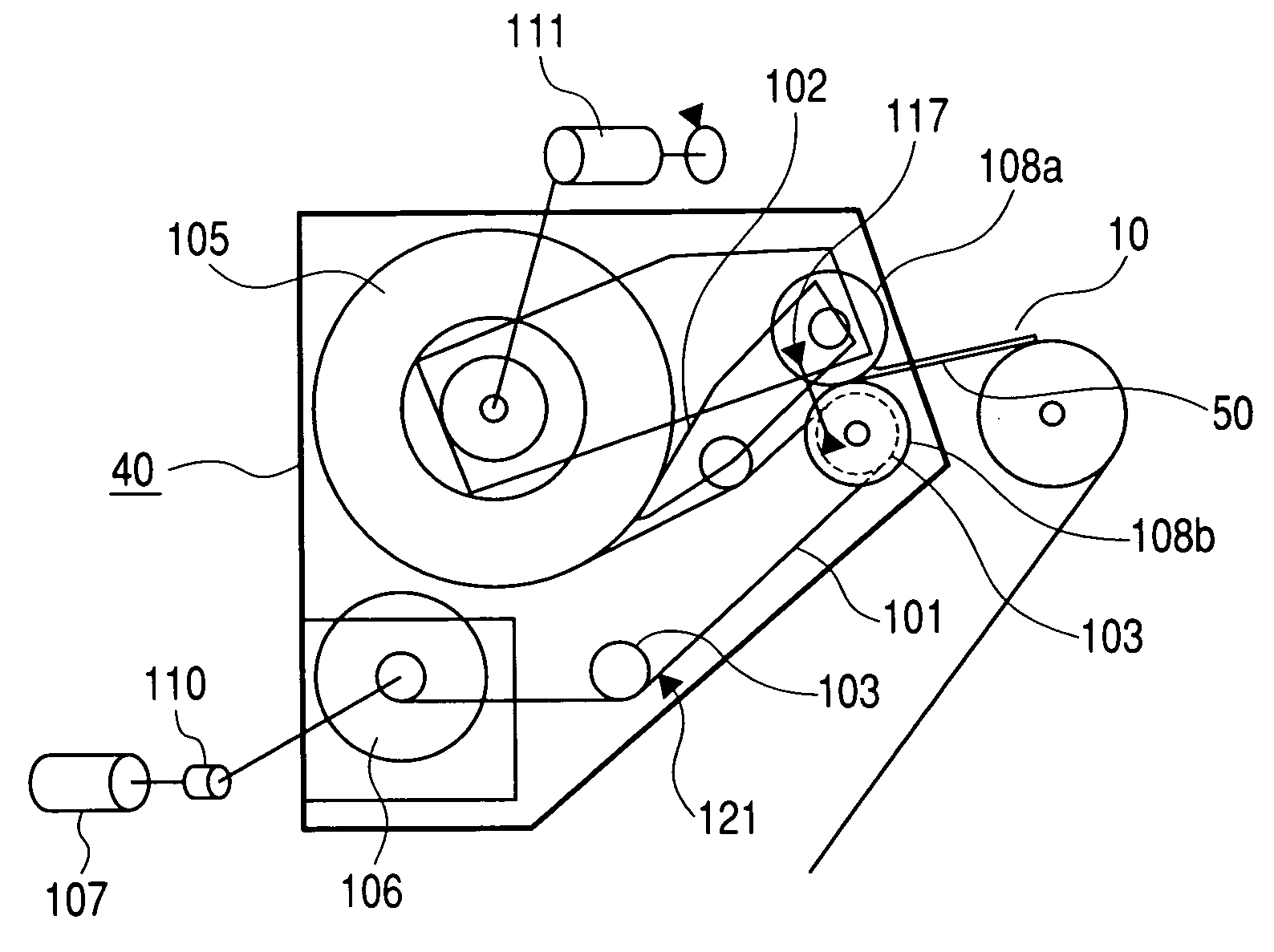
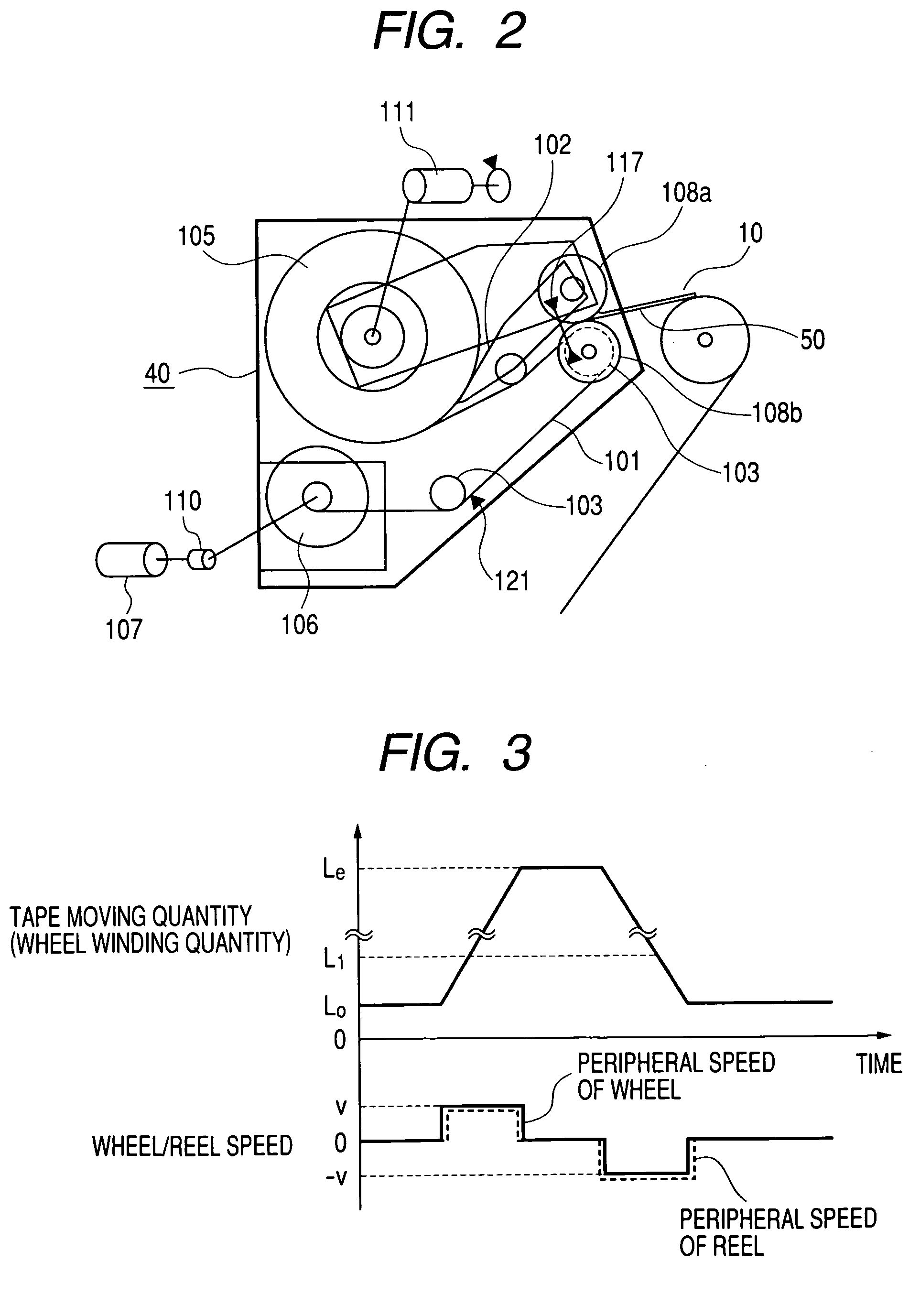
[0050] Here, in the second embodiment, as shown in FIG. 9 and a portion A in FIG. 10, the reel drive motor 107 is finely started in the tape releasing direction 5a so as to weaken a tension imparted to the tape 101. Subsequently, the dust Y which is adhered to the tape 101 is made to fall due to the vibrations of the tape 101 which are generated when the reel driving motor 107 is started in the tape winding direction 5b so as to impart the tension to the tape 101 again.

third embodiment

[0051] Further, in the third embodiment, as shown in a portion B in FIG. 11, the wheel drive motor 111 is finely started in the tape releasing direction 7a so as to weaken a tension imparted to the tape 101. Subsequently, the dust Y which is adhered to the tape 101 is made to fall due to the vibrations of the tape 101 which are generated when the wheel drive motor 111 is started in the tape winding direction 7b so as to impart the tension to the tape 101 again.

fourth embodiment

[0052] Further, in the fourth embodiment, as shown in a portion C in FIG. 12, the wheel drive motor 111 and the reel drive motor 107 are finely started in the tape releasing directions 7a and 5a so as to weaken a tension imparted to the tape 101. Subsequently, the dust Y which is adhered to the tape 101 is made to fall due to the vibrations of the tape 101 which are generated when the wheel drive motor 111 and the reel drive motor 107 are started in the tape winding directions 7b and 5b so as to impart the tension to the tape 101 again.

[0053] As described above, although the dust is made to fall only by the gravity in the first embodiment which is explained in conjunction with FIG. 6, according to the second to the fourth embodiments, the control is made to impart the vibrations to the tape and hence, it is possible to make the dust adhered to the tape fall more effectively and hence, the dust which remains on the tape can be further reduced.

[0054] With respect to the reverse rotat...


PUM

PropertyMeasurementUnit
Tensionaaaaaaaaaa

Abstract

The present invention provides a paper sheet storing and releasing apparatus which stores and releases paper sheets by winding and unwinding a tape between a wheel and a reel, wherein the apparatus can remove dust stacked on the tape during an operation thereof and reduces damage on the tape. In the paper sheet storing and releasing apparatus which includes a reel which winds and unwinds a tape and a wheel which winds and unwinds the tape and paper sheets and in which running of the tape is stopped at a stop position which constitutes a reference, at the time of releasing the tape from the wheel, the releasing of the tape is temporarily stopped before the tape is stopped at the tape stop position which constitutes the reference and, thereafter, a tape winding operation of a given quantity is performed whereby the dust scraped by a scraper are made to fall and are transferred onto a tape side and the tape is released again so as to reduce a quantity of dust stacked at a final stop position of the tape.

Description

CROSS-REFERENCE TO RELATED APPLICATION [0001] The present application claims priority from Japanese application JP 2003-157523 filed on Jun. 3, 2003, the content of which is hereby incorporated by reference into this application. BACKGROUND OF THE INVENTION [0002] The present invention relates to a paper sheet storing and releasing apparatus which handles paper sheets such as bills and checks, and more particularly to a paper sheet storing and releasing device adopting a method which stores paper sheets by winding the paper sheets together with a tape around a wheel and feeds the paper sheets by rewinding the tape wound around the wheel. [0003] There has been known a paper sheet storing and releasing apparatus in which paper sheets are stored by connecting both ends of a tape to a wheel and a reel and by winding the tape in a state that the paper sheets are sandwiched between the wheel and the tape and the paper sheets are fed by rewinding the tape to the reel so as to release the t...

Claims


Application Information

Patent Timeline
IPC IPC(8): G07D9/00B65H5/28B65H23/18B65H23/28
CPCB65H5/28B65H2301/4191B65H2513/41B65H2513/512B65H2557/33B65H2701/1912B65H2220/02B65H29/006
Inventor ICHIKAWA, HIROSHIKOSHIZUKA, HISAHIROKATO, RIICHINIIOKA, YASUNARI
Owner HITACHI CHANNEL SOLUTIONS CORP
Why Eureka
Try Eureka