Method and system for controlling brake-application energy in a vehicle combination

Active Publication Date: 2005-01-27
WABCO GMBH
View PDF5 Cites 44 Cited by
  • Summary
  • Abstract
  • Description
  • Claims
  • Application Information

AI Technical Summary

Benefits of technology

The present invention accordingly comprises the various steps and the relation of one or more of such steps with respect to each of the others, and embodies features of construction, combinations o

Problems solved by technology

The total braking performance is adjusted only via the trailer vehicle, with the disadvantage that any temperature difference that may exist between the wheel brakes of the trailer vehicle and tractor vehicle becomes even greater due to this control.
Another disadvantage of the method described in EP 0 697 314 B1 is that vehicle deceleration c

Method used


Image

  • Method and system for controlling brake-application energy in a vehicle combination
  • Method and system for controlling brake-application energy in a vehicle combination
  • Method and system for controlling brake-application energy in a vehicle combination

Examples


Embodiment Construction

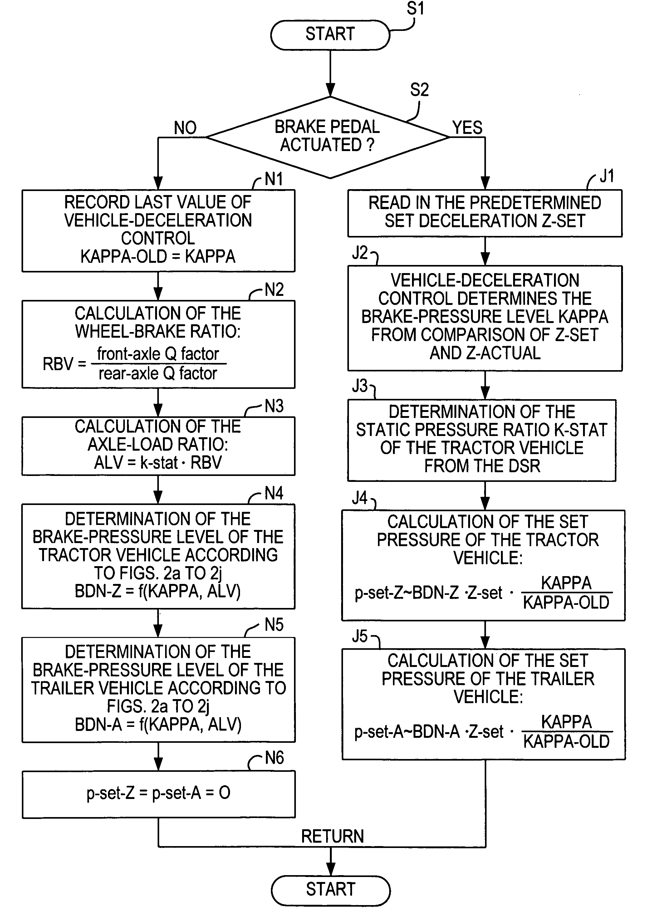
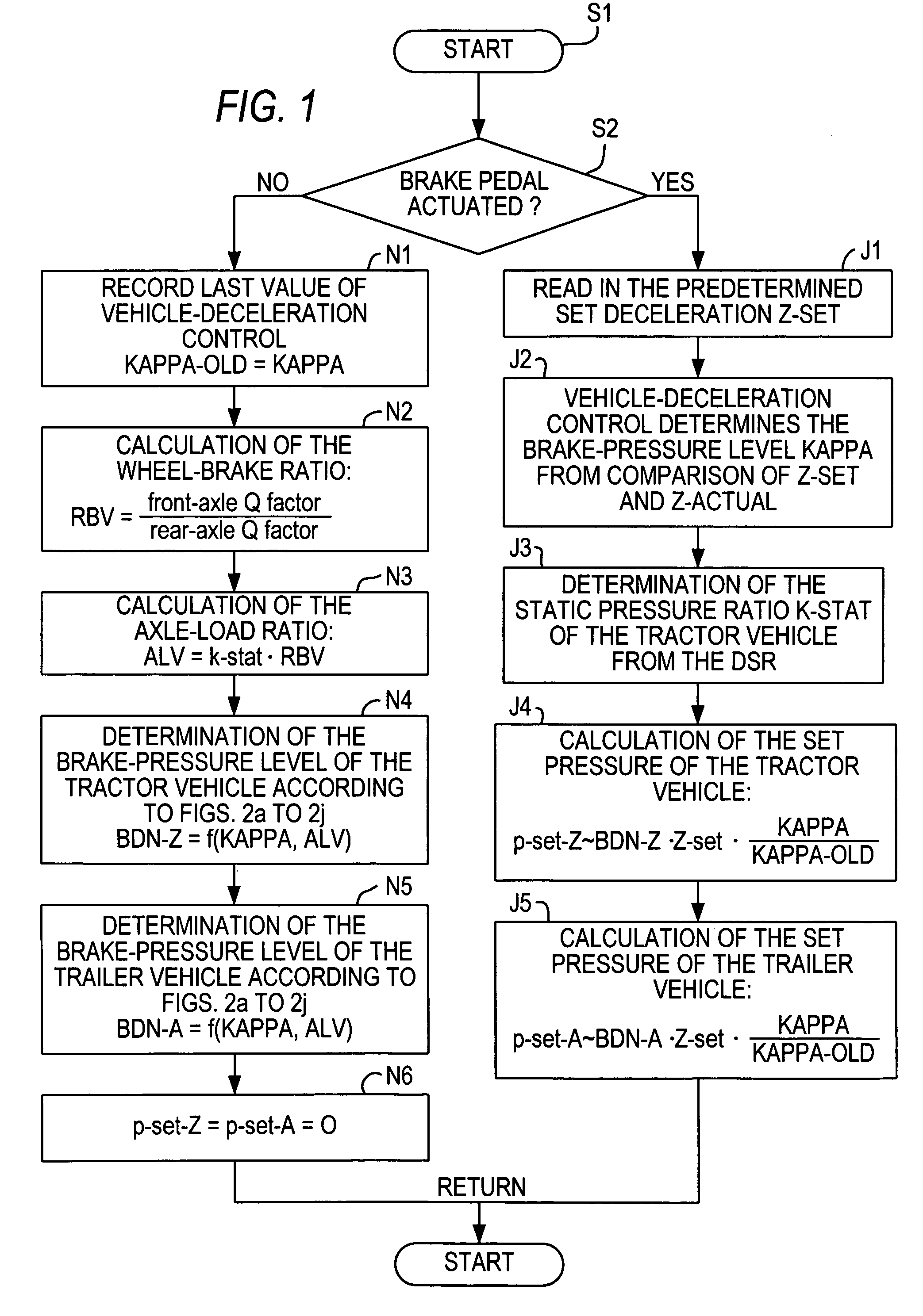
Referring now to the drawing figures, FIG. 1 depicts a process for controlling brake-application energy in a vehicle combination (which includes a tractor vehicle equipped with an EBS as well as a trailer vehicle) according to a preferred embodiment of the present invention (brake-application energy being expressed as brake pressure or pressure). After the start in step S1, a check is conducted to ascertain whether the brake pedal has been actuated or a brake value transmitter signal is being output (step S2). If this is the case, a set deceleration value Zset is generated from the brake value transmitter signals and read in (step J1).

In a subsequent step J2, a brake-application energy reference value (kappa) is determined. The vehicle deceleration control function determines kappa from a comparison of the set deceleration value Zset with actual deceleration value Zactual.

In a subsequent step J3, a differential slip control function (DSR) of the EBS determines the static ratio ...


PUM


Abstract

A method and system for controlling brake-application energy in a tractor-trailer vehicle combination, the tractor vehicle having an electronic braking system (EBS), wherein, during braking, a set deceleration value is determined and compared with an actual deceleration value, and a current brake-application energy reference value (kappa) is determined from the comparison. To effect automatic load-dependent brake-force control for the trailer vehicle and to realize rapid adaptation of the control system to driving and load conditions, set brake-application energy values for each of the tractor and trailer vehicles are determined from the set deceleration value, from a value depending on kappa, and from brake-application energy levels for each of the tractor and trailer vehicles, using sets of performance characteristics resident in the EBS to describe the dependencies of the brake-application energy levels for the tractor and trailer vehicles on kappa and/or on the axle-load ratio of the tractor vehicle.

Description

BACKGROUND OF THE INVENTION The present invention is directed generally to a method and system for controlling brake-application energy in a vehicle combination including a tractor vehicle equipped with an electronic braking system (EBS) and a trailer vehicle. It is known that vehicle combinations (comprising a tractor vehicle having front and rear axles as well as a trailer vehicle) can be provided, on the one hand, with a vehicle deceleration control function, otherwise known as “Z-control,” and, on the other hand, with coupling force control between the tractor vehicle and the trailer vehicle. EP 0 697 314 B1 describes, for load-dependent control of brake pressure in a vehicle combination, a method designed to brake the trailer and tractor vehicles as equally as possible by appropriate distribution of brake pressure to the axles of the tractor vehicle and trailer vehicle. For this purpose, an initial value of a reference factor is determined by means of a set of performance ch...

Claims


Application Information

Patent Timeline
IPC IPC(8): B60T8/30B60T8/17B60T8/1766B60T8/32B60T13/68
CPCB60T13/683B60T8/1708
Inventor ECKERT, HORSTGAULKE, ARND
Owner WABCO GMBH
Why Eureka
Try Eureka