Image display apparatus and method of driving image display apparatus

a technology of image display and display apparatus, which is applied in the direction of instruments, television systems, static indicating devices, etc., can solve the problems of low response speed of cold cathode devices, and inability to precisely show the actual position and shape of electron-emitting portions. , to achieve the effect of high quality

Inactive Publication Date: 2005-01-27
CANON KK
View PDF41 Cites 4 Cited by
  • Summary
  • Abstract
  • Description
  • Claims
  • Application Information

AI Technical Summary

Benefits of technology

[0019] It is an object of the present invention to realize an image display apparatus capable of displaying various kinds of signals with high quality in an arrangement in which a plurality of display devices are commonly wired, and a driving method thereof.

Problems solved by technology

However, this does not exactly show the actual position and shape of the electron-emitting portion.
Even if a large number of devices are arranged on a substrate at a high density, problems such as heat fusion of the substrate hardly arise.
In addition, the response speed of the cold cathode device is high, while the response speed of the thermionic cathode device is low because thermionic cathode device operates upon heating by a heater.

Method used


Image

  • Image display apparatus and method of driving image display apparatus
  • Image display apparatus and method of driving image display apparatus
  • Image display apparatus and method of driving image display apparatus

Examples


first embodiment

[0091] The first embodiment concerns an example of modulation using a voltage pulse width-modulated signal as a modulated signal in order to obtain a desired image in a display apparatus having many surface-conduction type emission devices.

[0092]FIG. 4 is a partially cutaway perspective view of the display panel used in the first embodiment showing the internal structure of the panel. In FIG. 4, reference numeral 1005 denotes a rear plate; 1006, a side wall; and 1007, a face plate. These parts 1005 to 1007 constitute an airtight container for maintaining the inside of the display panel vacuum. To construct the airtight container, it is necessary to seal-connect the respective parts to obtain sufficient strength and maintain airtight condition. For example, frit glass is applied to junction portions, and sintered at 400 to 500° C. in air or nitrogen atmosphere, thus the parts are seal-connected. A method for exhausting air from the inside of the container will be described later.

[0...

second embodiment

[0139] The second embodiment concerns an example of modulation using a voltage amplitude-modulated signal as a modulated signal in order to obtain a desired image in a display apparatus having many surface-conduction type emission devices.

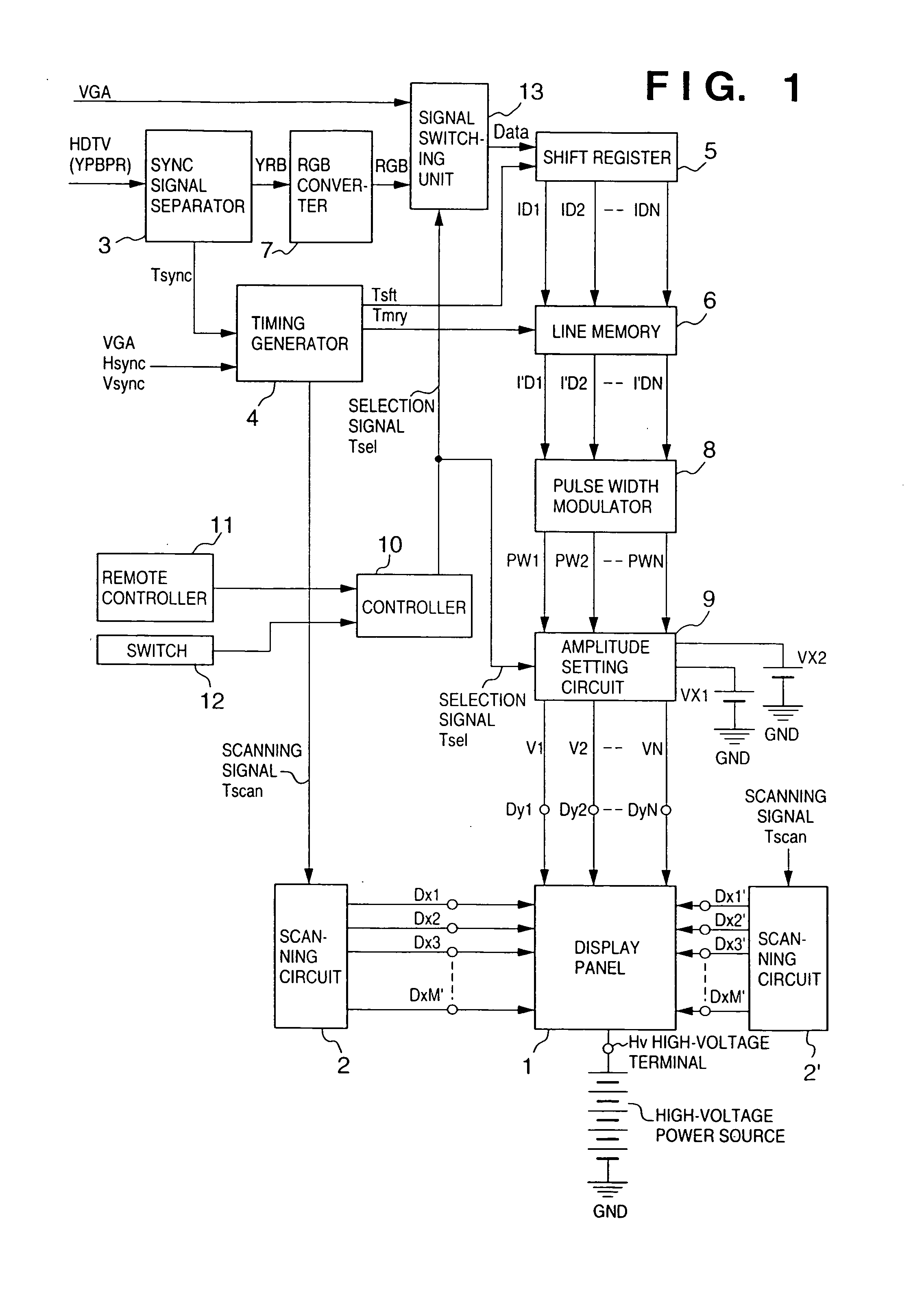
[0140]FIG. 8 is a block diagram schematically showing a circuit arrangement. The second embodiment employs an amplitude modulator 21 instead of the pulse width modulator 8 in the first embodiment.

[0141] (Amplitude Modulator and Amplitude Setting Circuit)

[0142] Image data separated by a sync signal separator 3 is serial / parallel-converted by a shift register 5, and stored in a line memory 6 during one horizontal scanning period. The amplitude modulator 21 D / A-converts the image data stored in the line memory 6 to output amplitude-modulated potential signals AM1 to AMN. Two outputs Vr1 and Vr2 of an amplitude setting circuit 22 are connected to the reference terminal of a D / A converter. The amplitudes (potential values) of the amplitude-modulated ...

third embodiment

[0158] When the above-described image display apparatus displays a natural image represented by the above-mentioned HDTV signal or another TV signal, the user can enjoy a wide-dynamic-range image with reality. When the apparatus displays a computer image represented by a VGA signal, the user hardly perceives any unnatural pattern caused by the voltage drop on the wiring. The apparatus can attain satisfactory characteristics as the output monitor of the computer.

[0159] The present inventors have examined an application to an image display apparatus having a display panel in which electroluminescent devices (EL) were arranged in a simple matrix structure as the image display device of the display panel. As a result, the same effects as described above could be obtained.


PUM


Abstract

An image display apparatus includes row wiring, a plurality of column wirings, a modulator, and a plurality of display devices. The plurality of display devices are commonly connected to the row wiring, each of the plurality of column wirings is connected to a corresponding one of the plurality of display devices, and the modulator supplies a modulated signal to the column wirings. The modulator includes a pulse width modulator for generating a pulse signal having a time width corresponding to the tone of a signal to be displayed, and a potential setting circuit for setting the potential of the pulse signal in accordance with the type of signal to be displayed.

Description

FIELD OF THE INVENTION [0001] The present invention relates to an image display apparatus and a method of driving the image display apparatus, particularly, to an image display apparatus constituted by commonly wiring a plurality of display devices and a driving method thereof, more particularly, to an image display apparatus having a display panel constituted by wiring a plurality of display devices in a matrix and a driving method thereof and, still more particularly, to an image display apparatus capable of displaying a television signal and computer video signal with high quality and a driving method thereof. BACKGROUND OF THE INVENTION [0002] Conventionally, two types of devices, namely thermionic and cold cathode devices, are known as electron-emitting devices. Known examples of the cold cathode devices are surface-conduction type emission devices, field emission type electron-emitting devices (to be referred to as FE type electron-emitting devices hereinafter), and metal / insu...

Claims


Application Information

Patent Timeline
Patent Type & Authority Applications(United States)
IPC IPC(8): H04N5/66G09G3/20G09G3/22G09G3/30G09G3/36
CPCG09G3/2011G09G3/2014G09G3/22G09G2320/0626G09G2320/0223G09G2320/0233G09G2310/027
Inventor SAGANO, OSAMUABE, NAOTO
Owner CANON KK
Why Eureka
Try Eureka