
Method for controlling one or more temperature dependent optical properties of a structure and a system and product thereof

a technology of temperature dependent optical properties and a structure, applied in the field of photonic bandgap structures, can solve problems such as key issues that remain to be resolved, and achieve the effect of reducing cost, integration, and real estate complications

Inactive Publication Date: 2005-01-27
UNIVERSITY OF ROCHESTER
View PDF5 Cites 9 Cited by
  • Summary
  • Abstract
  • Description
  • Claims
  • Application Information

AI Technical Summary

Benefits of technology

The present invention is about controlling the temperature dependence of optical properties of a structure, such as a photonic band-gap device. By heating and oxidizing a portion of the structure, the invention makes it insensitive to temperature changes. This results in devices that are more stable and reliable, and can operate over a wider range of temperatures. The invention also eliminates the need for additional temperature-stabilizing components, reducing cost and complexity.

Problems solved by technology

However, before direct applications appear, some key issues remain to be resolved.

Method used


Image

  • Method for controlling one or more temperature dependent optical properties of a structure and a system and product thereof
  • Method for controlling one or more temperature dependent optical properties of a structure and a system and product thereof
  • Method for controlling one or more temperature dependent optical properties of a structure and a system and product thereof

Examples


Embodiment Construction

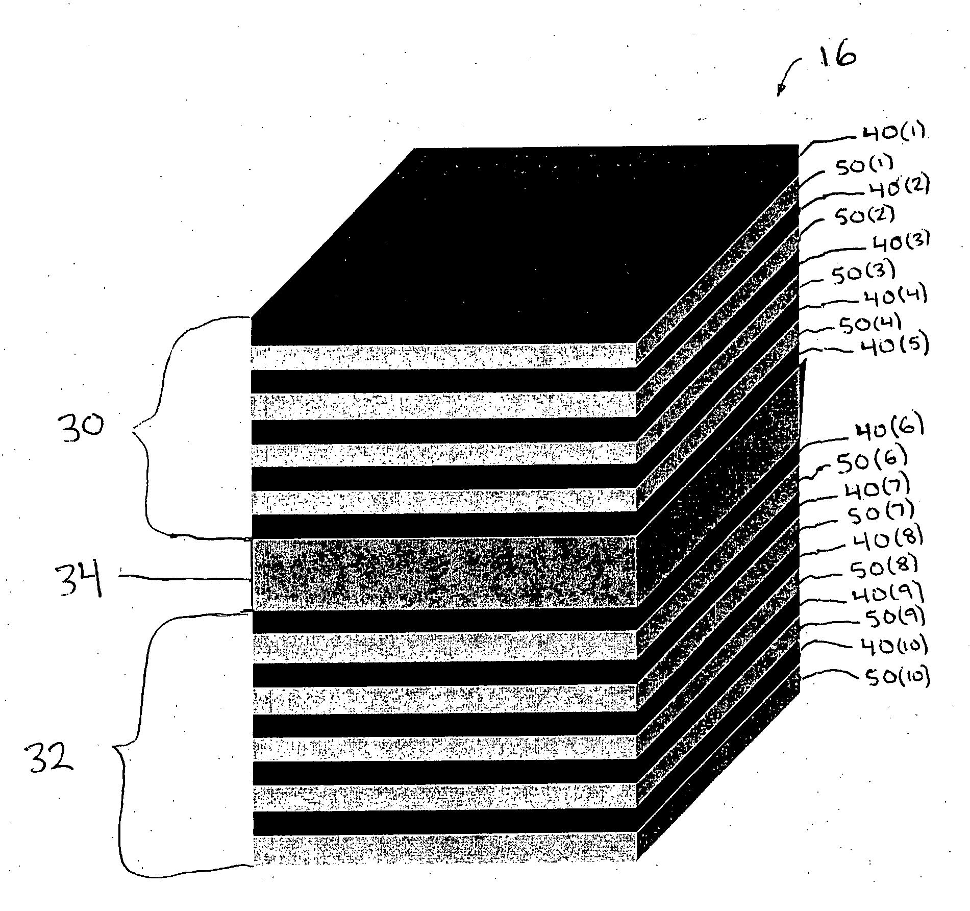
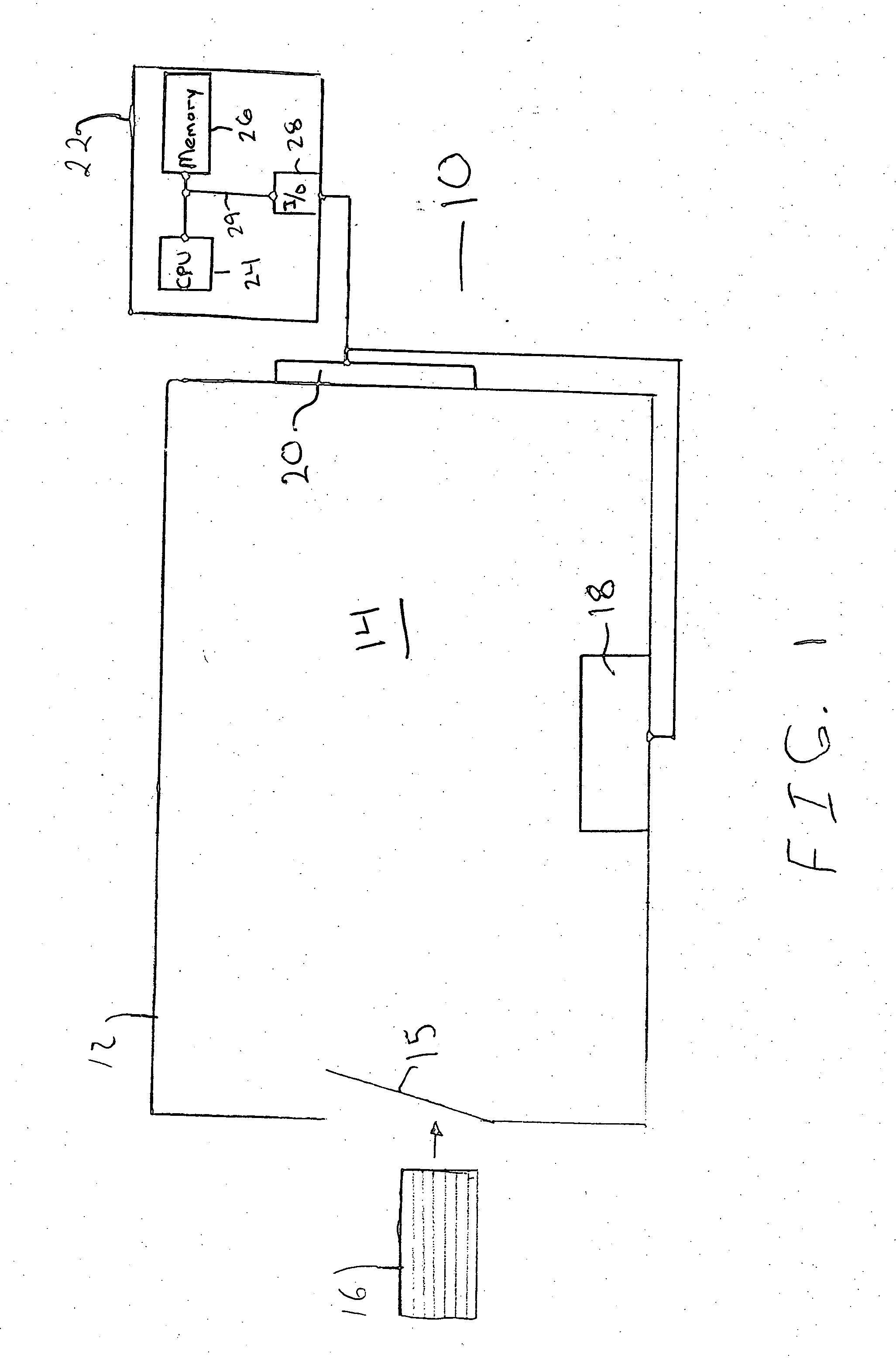
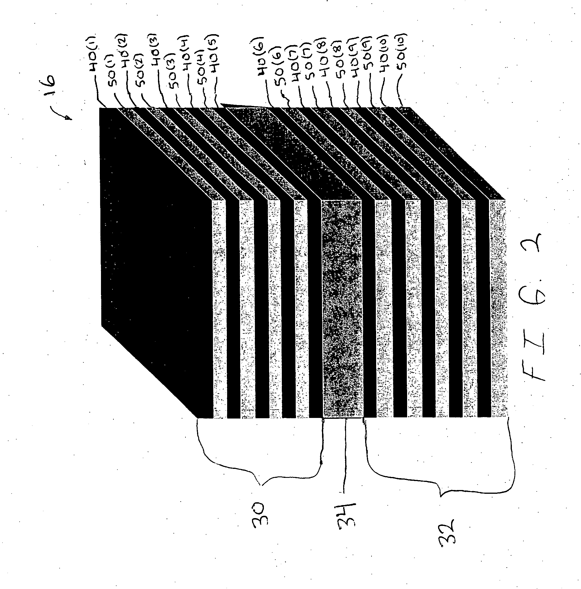
A system 10 and method for controlling one or more temperature dependent optical properties of a PBG structure or device 16 in accordance with embodiments of the present invention is illustrated in FIGS. 1-3. The system 10 includes a furnace 12 with a chamber 14 and a heating device 18 and an oxidizing device 20, although the system 10 can comprise other numbers and types of elements in other configurations. The present invention provides a number of advantages including minimizing the thermally induced drift of the reflectance spectra of a PBG structure 16.

Referring to FIG. 1, the furnace 12 includes a chamber 14 with a door 15 which are both sized to receive the PBG structure 16, although types of configurations for the furnace 12 can be used. The furnace 12 is used to anneal and oxidize the PBG structure 16 in the chamber 14 to control one or more temperature dependent optical properties of the PBG structure 16, although other types of devices for annealing or heating and oxidiz...


PUM


Abstract

A method for controlling one or more temperature dependent optical properties of a structure in accordance with embodiments of the present invention includes heating at least a portion of a photonic band-gap structure and oxidizing the portion of the photonic band-gap structure during the heating to alter at least one temperature dependent optical property of the stack.

Description

FIELD This invention generally relates to photonic band-gap structures and, more particularly, to a method for controlling one or more temperature dependent optical properties in a photonic band-gap structure and a system and resulting product thereof. BACKGROUND For more than a decade, photonic band-gap (PBG) structures have received a great deal of attention due to their ability to control the propagation of light as disclosed in E. Yablonovitch, Phys. Rev. Lett. 58, 2059 (1987); S. John, Phys. Rev. Lett. 58, 2486 (1987), which is herein incorporated by reference in its entirety. A photonic band-gap device is a macroscopic, periodic dielectric structure that possesses spectral gaps (stop bands) for electromagnetic waves, in analogy with the energy bands and gaps in regular semiconductors. PBG materials possess a periodic dielectric function that creates a range of wavelengths in which light cannot travel. Inserting a defect into the PBG structure breaks the periodicity of the di...

Claims


Application Information

Patent Timeline
Patent Type & Authority Applications(United States)
IPC IPC(8): G02B6/122
CPCG02B6/1225B82Y20/00
Inventor WEISS, SHARON M.FAUCHET, PHILIPPE M.MOLINARI, MICHAEL
Owner UNIVERSITY OF ROCHESTER
Learn More