Microfluidic nozzle formation and process flow

a microfluidic and micromechanical technology, applied in the direction of pipe heating/cooling, inking apparatus, transportation and packaging, etc., can solve the problems of reducing the manufacturing cost and retail price of such devices, and affecting the quality of the produ

Active Publication Date: 2010-07-01
STMICROELECTRONICS SRL
View PDF16 Cites 12 Cited by
  • Summary
  • Abstract
  • Description
  • Claims
  • Application Information

AI Technical Summary

Benefits of technology

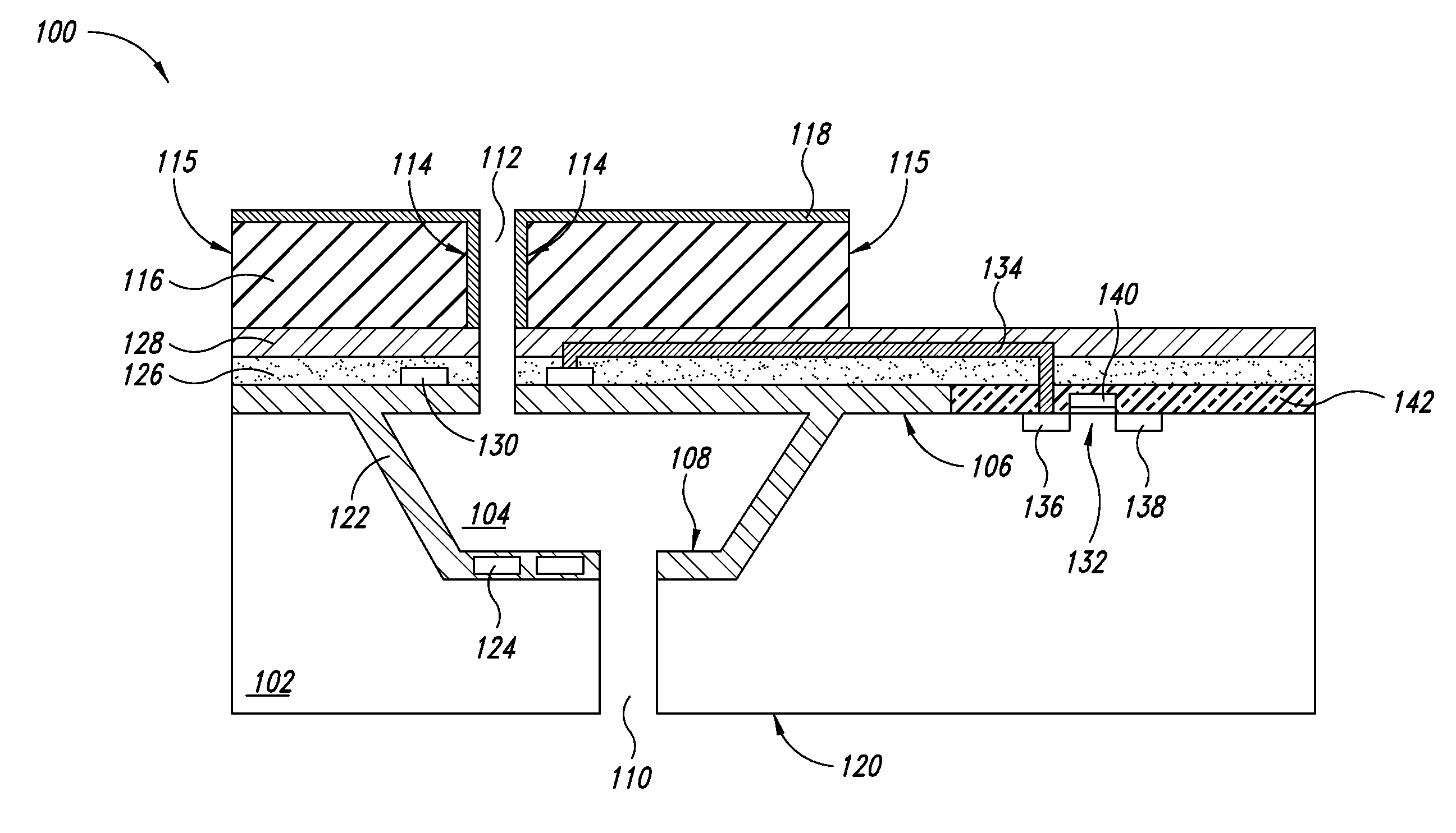
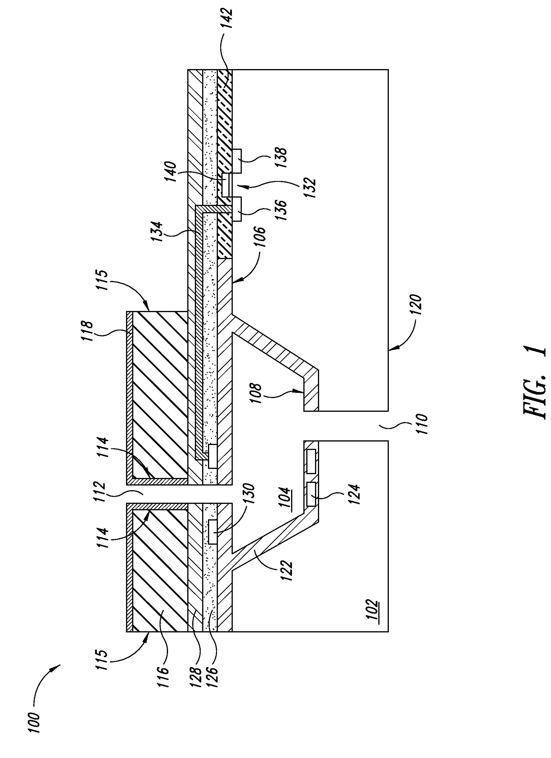
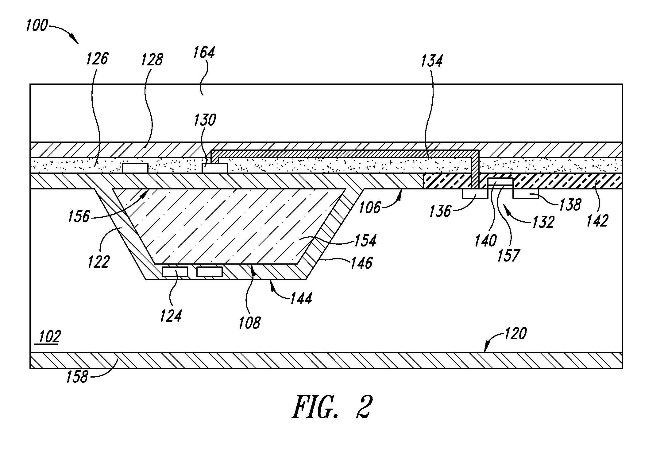
[0012]Subsequently, a metal layer is deposited on the passivation layer and around the pillar. The pillar is then removed. The metal layer provides the walls of the nozzle once the pillar is removed. The pillar can be removed simultaneously with the formation of the inlet path through a back side of the substrate. Preferably, the metal layer is tungsten, aluminum, or copper. A protection layer is then deposited over the metal layer as a protection from the corrosive properties of the fluid that will pass through the nozzle. The protection layer is significantly thinner than the metal layer. In one embodiment, the metal layer is 15-17 microns thick and the protection layer is 0.2-1 microns.

Problems solved by technology

Accordingly, manufacturing large quantities of such devices requires large quantities of gold, significantly adding to the cost of manufacturing and the retail price of such devices.
In addition, the process to form the large gold layer and define the nozzle is difficult and time consuming.
These processes complicate manufacturing and are difficult to control.
The significant amount of gold, the application of the protection layers, and the sensitivity problem add to the cost of manufacturing and the ultimate retail price of such devices.

Method used


Image

  • Microfluidic nozzle formation and process flow
  • Microfluidic nozzle formation and process flow
  • Microfluidic nozzle formation and process flow

Examples


Embodiment Construction

[0020]In the following description, certain specific details are set forth in order to provide a thorough understanding of various embodiments of the disclosure. However, one skilled in the art will understand that the disclosure may be practiced without these specific details. In other instances, well-known structures associated with electronic components and semiconductor fabrication have not been described in detail to avoid unnecessarily obscuring the descriptions of the embodiments of the present disclosure.

[0021]Unless the context requires otherwise, throughout the specification and claims that follow, the word “comprise” and variations thereof, such as “comprises” and “comprising,” are to be construed in an open, inclusive sense, that is, as “including, but not limited to.”

[0022]Reference throughout this specification to “one embodiment” or “an embodiment” means that a particular feature, structure or characteristic described in connection with the embodiment is included in a...


PUM


Abstract

A method that includes forming a chamber in a substrate, forming a silicon layer overlying the chamber, etching the silicon layer to remove selected regions and retain a selected portion overlying the chamber, the selected portion being at a location and having dimensions that correspond to a location and to dimensions of a nozzle, and forming a first metal layer adjacent to the selected portion. The method also includes forming a path in the substrate to expose the chamber concurrently with removing the selected portion of the silicon layer to expose the nozzle, the nozzle being in fluid communication with the path, the chamber, and a surrounding environment.

Description

BACKGROUND[0001]1. Technical Field[0002]The present disclosure relates to a process of forming a nozzle opening for microfluidic and micromechanical chambers and, more particularly, to forming a nozzle with minimal amounts of gold.[0003]2. Description of the Related Art[0004]In applications using microfluidic structures or micro-electro mechanical structures (MEMS), fluid is often held in a chamber where it is heated. In addition, some fluids are processed at temperatures that need to be accurately regulated. The most common application is inkjet printer heads. Current inkjet technology relies on placing a small amount of ink within an ink chamber, rapidly heating the ink and ejecting it to provide an ink drop at a selected location on an adjacent surface, such as a sheet of paper. Other applications include analyzing fluids with organic components, such as enzymes and proteins, processing biological examinations, and amplifying DNA.[0005]A DNA amplification process (PCR, i.e., Poly...

Claims


Application Information

Patent Timeline
Patent Type & Authority Applications(United States)
IPC IPC(8): F16L53/00B44C1/22
CPCB41J2/14056B41J2/1601B41J2/1628B41J2/1629B41J2/1631B41J2/1639B41J2/1642B41J2/1643B41J2/1646B41J2002/1437B41J2202/16Y10T137/6416
Inventor FANG, MINGWANG, FUCHAO
Owner STMICROELECTRONICS SRL
Why Eureka
Try Eureka