

Method and Devices For Cardiac Valve Annulus Expansion
a technology of annulus expansion and cardiac valve, which is applied in the field of cardiac valve annulus expansion device, can solve the problems of uncompensated heart energy deficit, inability to carry out coronary perfusion, and premature death, and achieve the effect of reducing the number of reoperations of patients and avoiding added operative time and potential complications
- Summary
- Abstract
- Description
- Claims
- Application Information
AI Technical Summary
Benefits of technology
Problems solved by technology
Method used
Image

Examples
example
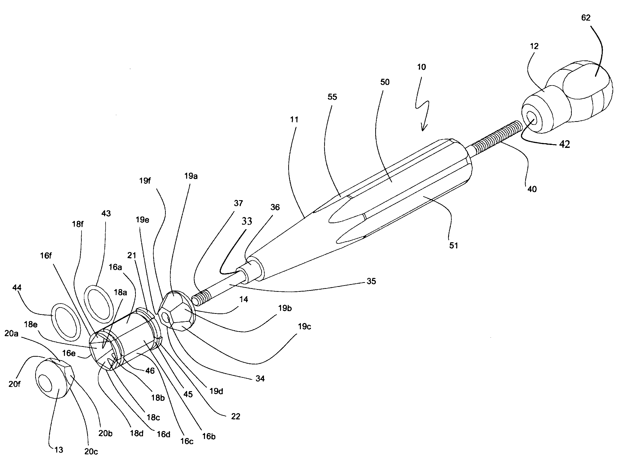
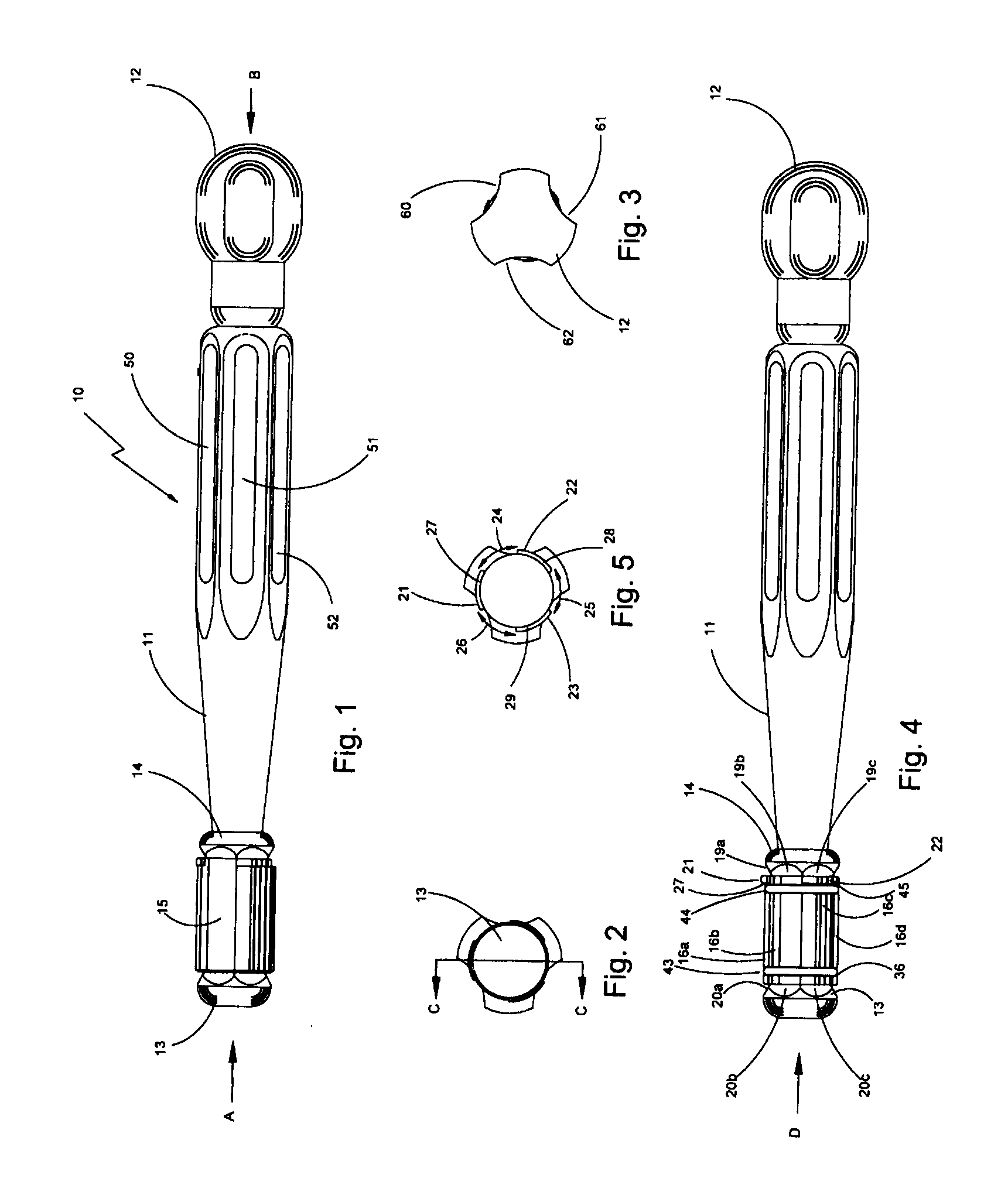
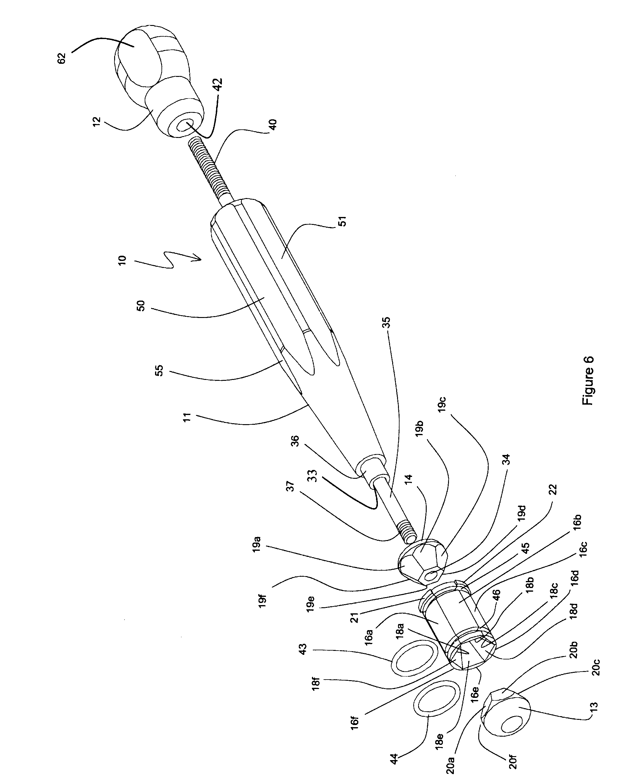
Structure
[0048]A prototype embodiment had an outer diameter of the assembled expansive member in its initial condition of 17.7 mm and the outer diameter measured across the midpoints of the expansive member in its expanded state of 22.9 mm. The irreversible dilation member 15 was made from laser cut stainless steel 0.006″ thick, using a flat pattern similar to that shown in FIG. 13 (but shorter and with two fewer columns of fenestrations, and without the two lugs 174, 175 and corresponding holes 174, 175). The strip was rolled into a spiral cylinder using a small, purpose built roll bender. A dead pig heart was procured, the aorta opened and the aortic annulus size measured using an ATS Medical, Inc. aortic valve sizer. A 19 mm sizer was found to be a smug fit in the aortic annulus, but it could be pushed though the annulus with slight force. A 21 mm sizer would not go into the aortic annulus, but could be forced through using high force. The sizer was pulled out and the 19 mm sizer...
PUM
 Abstract
Description
Claims
Application Information