Spatial light modulator and projector

Inactive Publication Date: 2005-01-27
SEIKO EPSON CORP
View PDF7 Cites 20 Cited by
  • Summary
  • Abstract
  • Description
  • Claims
  • Application Information

AI Technical Summary

Benefits of technology

is to provide a spatial light modulator and a projector that display a smooth image of a

Problems solved by technology

However, the periodic arrangement of the pixels causes a sampling noise that deteriorates quality of the image, which makes the image rough and less smooth.
For this reason, a watcher may recognize a black matrix image in a conventional dot-matrix image display device, resulting in the deterioration of the quality of the image.
As a result, the black matrix image becomes hard to

Method used


Image

  • Spatial light modulator and projector
  • Spatial light modulator and projector
  • Spatial light modulator and projector

Examples


Embodiment Construction

Exemplary embodiments of a spatial light modulator and a projector according to the present invention are explained in detail with reference to the accompanying drawings.

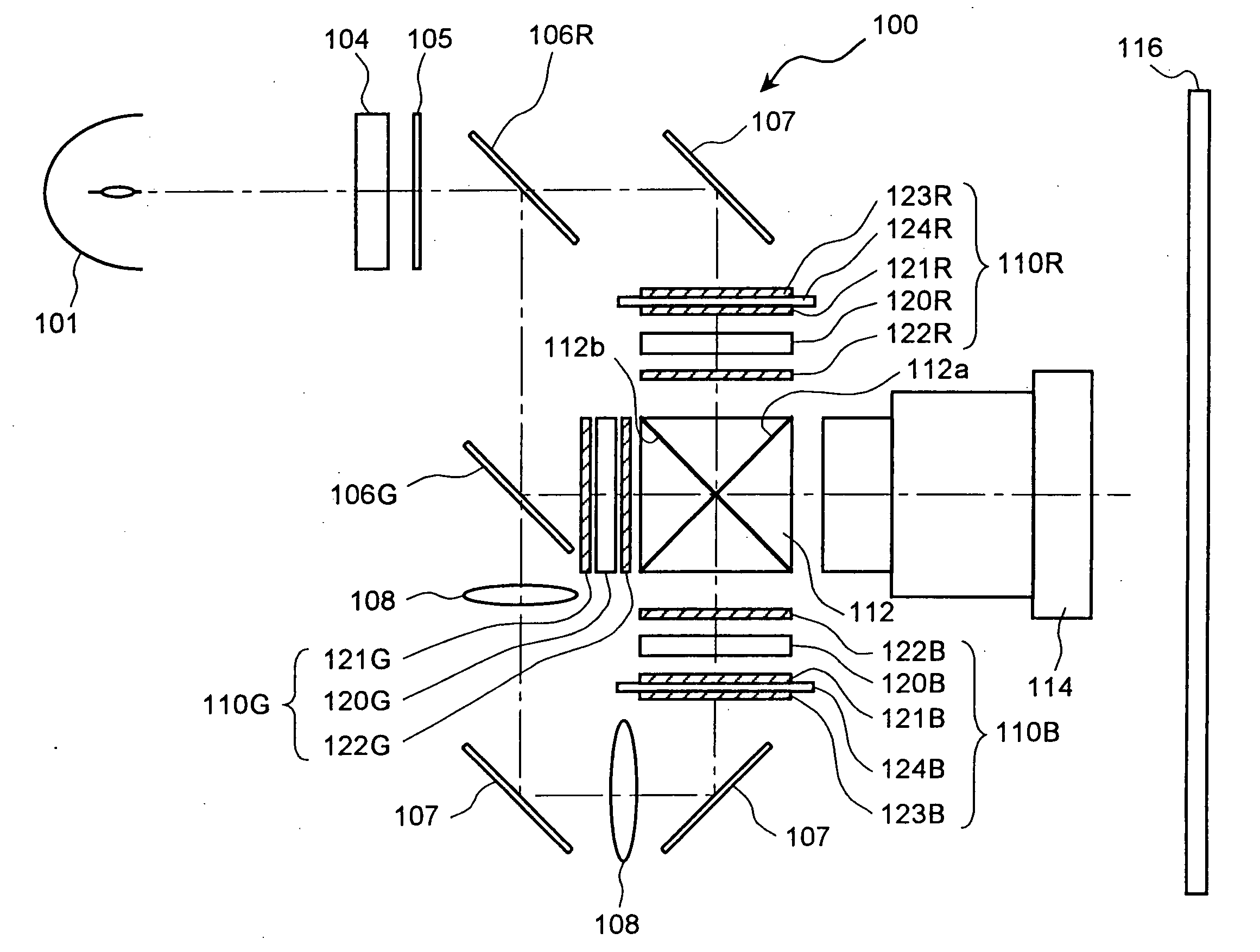
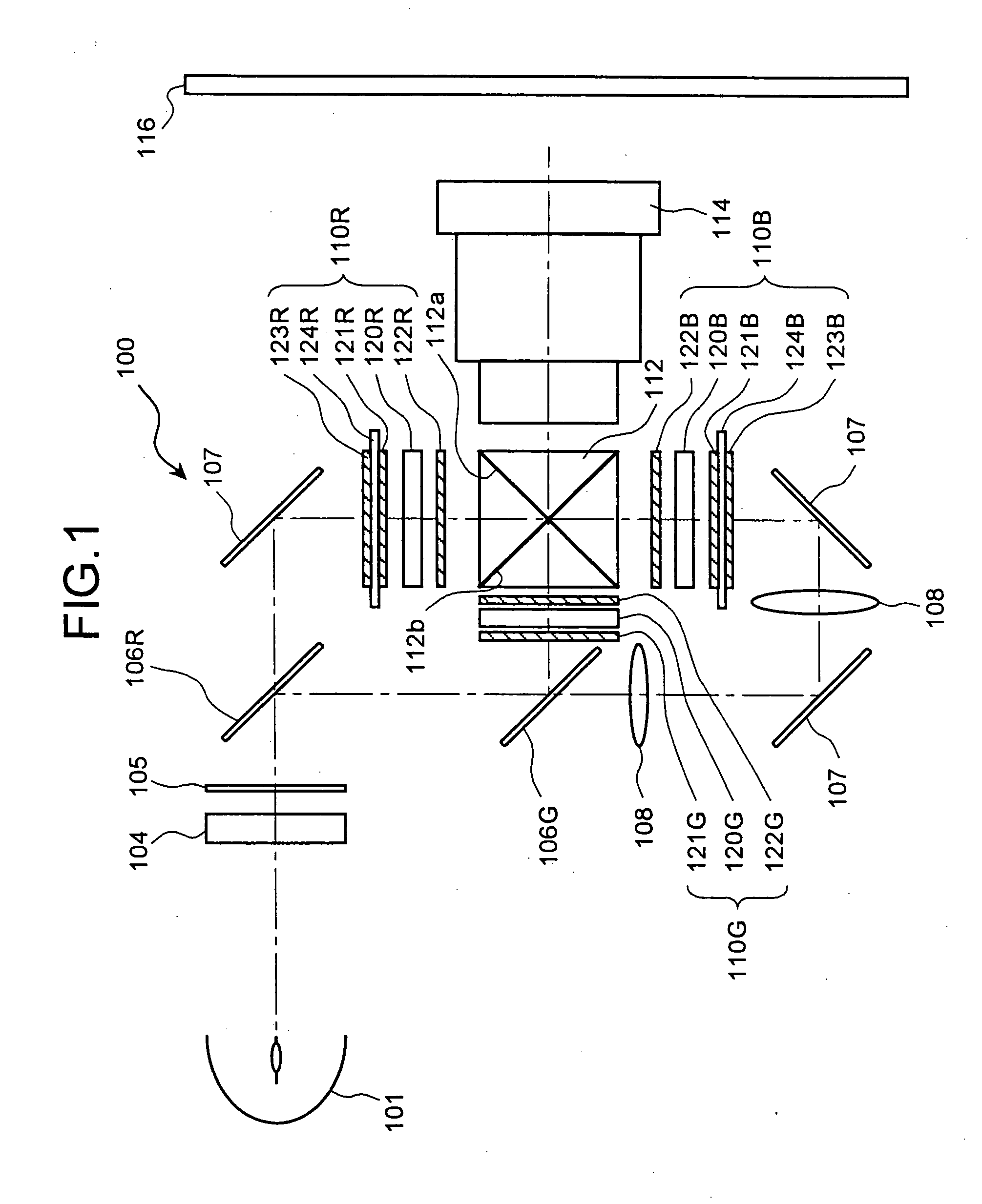
FIG. 1 is a schematic of a projector according to a first embodiment of the present invention. A super-high pressure mercury lamp 101 generates a light that includes a red light, a green light, and a blue light (hereinafter, “R-light”, “G-light”, and “B-light”, respectively). An integrator 104 uniforms an illuminance distribution of the light. A polarization converter 105 changes the light with the uniform illuminance-distribution into a polarized light such as an s-polarized light. The s-polarized light enters into a red-light transmitting dichroic mirror 106R. The red-light transmitting dichroic mirror 106R transmits the R-light, but reflects the G-light and the B-light. The dichroic mirrors separate the light into the R-light, the G-light, and the B-light in order.

After the R-light passes through the red-ligh...


PUM


Abstract

A spatial light modulator includes a prism group and satisfies either of the following conditions
d<0.95×λ/(2×(n−1)),
d>1.05×λ/(2×(n−1))
where d is a distance between a reference surface and a flat surface, λ is a wavelength of an incident light, and n is a refractive index of the prism group.

Description

BACKGROUND OF THE INVENTION 1) Field of the Invention The present invention relates to a spatial light modulator and a projector, and more particularly, to a liquid-crystal spatial light modulator. 2) Description of the Related Art A dot-matrix display device is widely used as an image display device, such as a liquid crystal panel (a liquid crystal display device), a cathode ray tube (CRT) display device, and a plasma display device. The dot-matrix display device displays an image by a number of pixels that are arranged periodically in two dimensional arrays. However, the periodic arrangement of the pixels causes a sampling noise that deteriorates quality of the image, which makes the image rough and less smooth. One of the methods to reduce deterioration of the quality of the image is disclosed in, for example, Japanese Patent Application Laid-Open No. H8-122709. The dot-matrix image display device has a light-shielding portion called a black matrix. The black matrix is an ar...

Claims


Application Information

Patent Timeline
IPC IPC(8): G02B5/04G02F1/13G02F1/1335G03B21/00H04N5/74H04N9/31H04N17/00
CPCG02B5/045G02F1/133504H04N9/3197H04N9/3105H04N5/7441G02F1/13
Inventor KAMIJIMA, SHUNJI
Owner SEIKO EPSON CORP
Why Eureka
Try Eureka