DC regulated power supply

Inactive Publication Date: 2005-01-27
SHARP KK
View PDF15 Cites 27 Cited by
  • Summary
  • Abstract
  • Description
  • Claims
  • Application Information

AI Technical Summary

Benefits of technology

[0009] An object of the present invention is to provide a DC regulated power supply which can

Problems solved by technology

However, in the foregoing conventional switching power supply, since the output sensing wires 13 extend closely to the load end, increase in the lengths of the power supply lines 10 results in an unstable control caused by noise and others.
Fur

Method used


Image

  • DC regulated power supply
  • DC regulated power supply
  • DC regulated power supply

Examples


first embodiment

[0018] The following will describe one embodiment of the present invention with reference to FIG. 1. Note that the present embodiment does not limit the scope of the present invention and is merely one example.

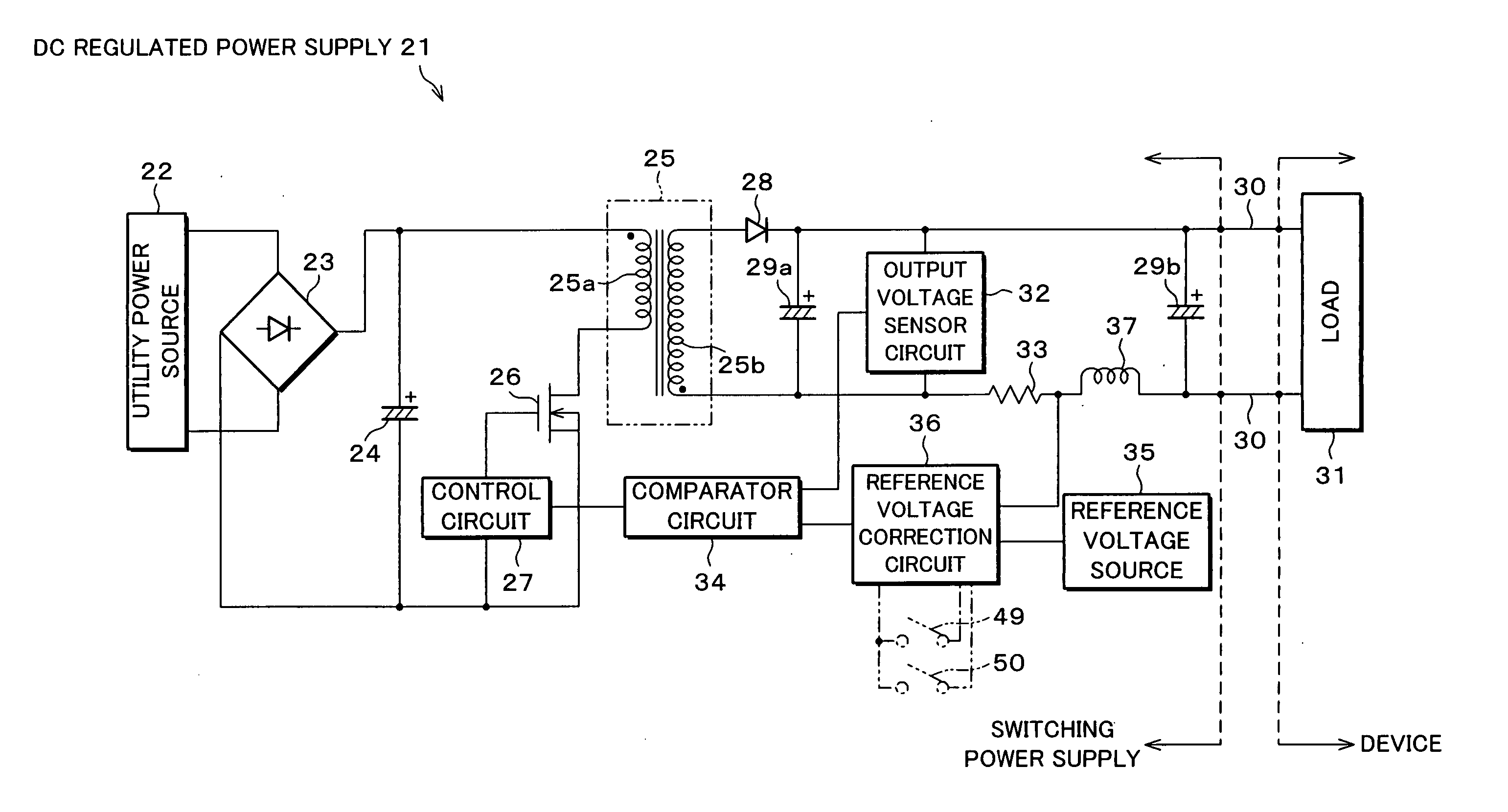
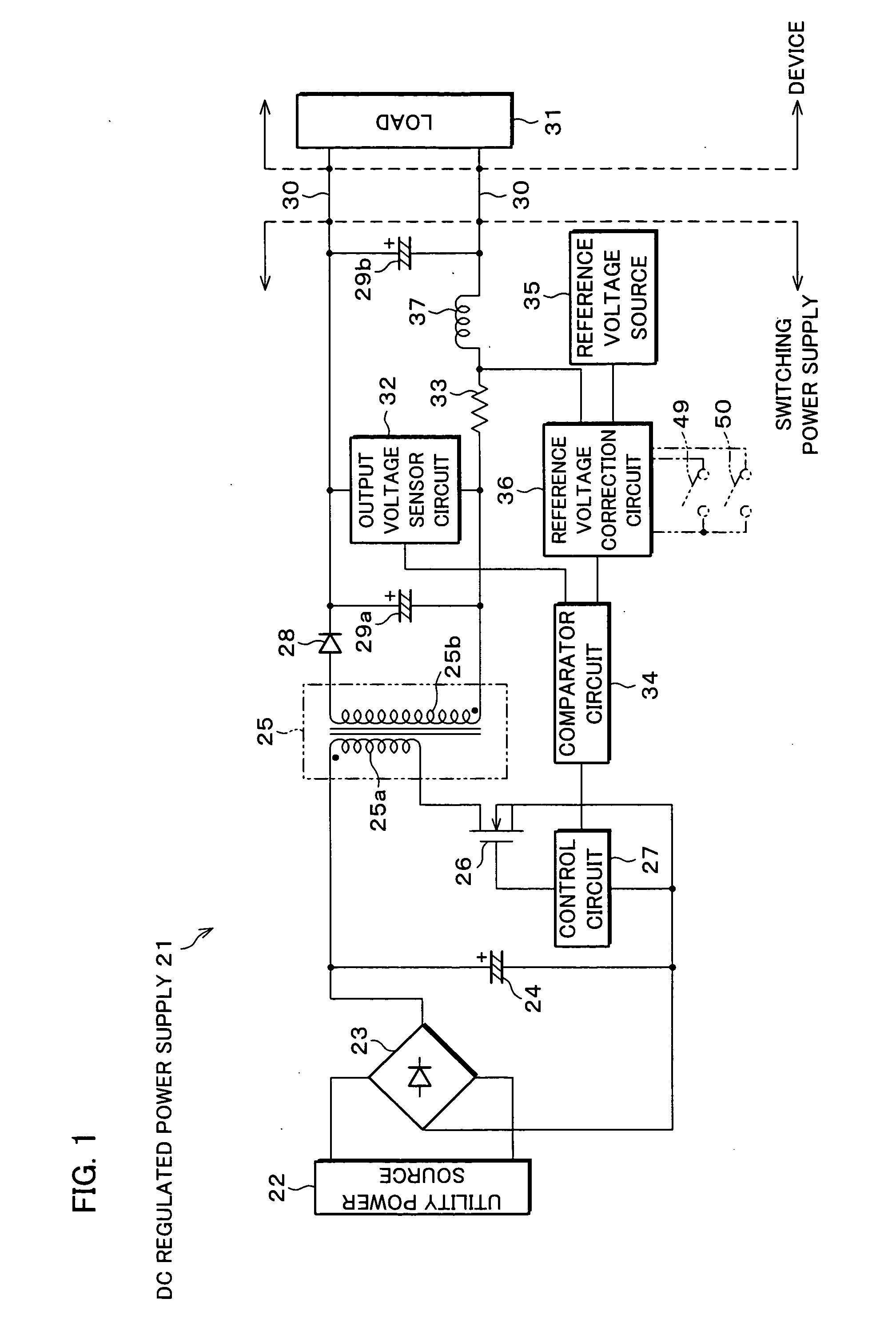
[0019]FIG. 1 is a block diagram illustrating an electrical arrangement of a DC regulated power supply 21 of one embodiment of the present invention. In the DC regulated power supply 21 that is a switching power supply used as the AC adapter, an AC input voltage from a utility power source 22 is transformed to a DC voltage by a rectifier diode 23 and a smoothing capacitor 24. The AC input voltage from the utility power source 22 becomes the DC voltage of the smoothing capacitor 24. That is, both ends of the smoothing capacitor 24 become a DC power supply. Across the DC power supply (between the both ends of the smoothing capacitor 24) connected is a series circuit of a primary winding 25a of a transformer 25 and a switching element 26, and the switching element 26 is intermitt...

second embodiment

[0028] The following will describe another embodiment of the present invention with reference to FIGS. 2 and 3, and the above-mentioned FIG. 1.

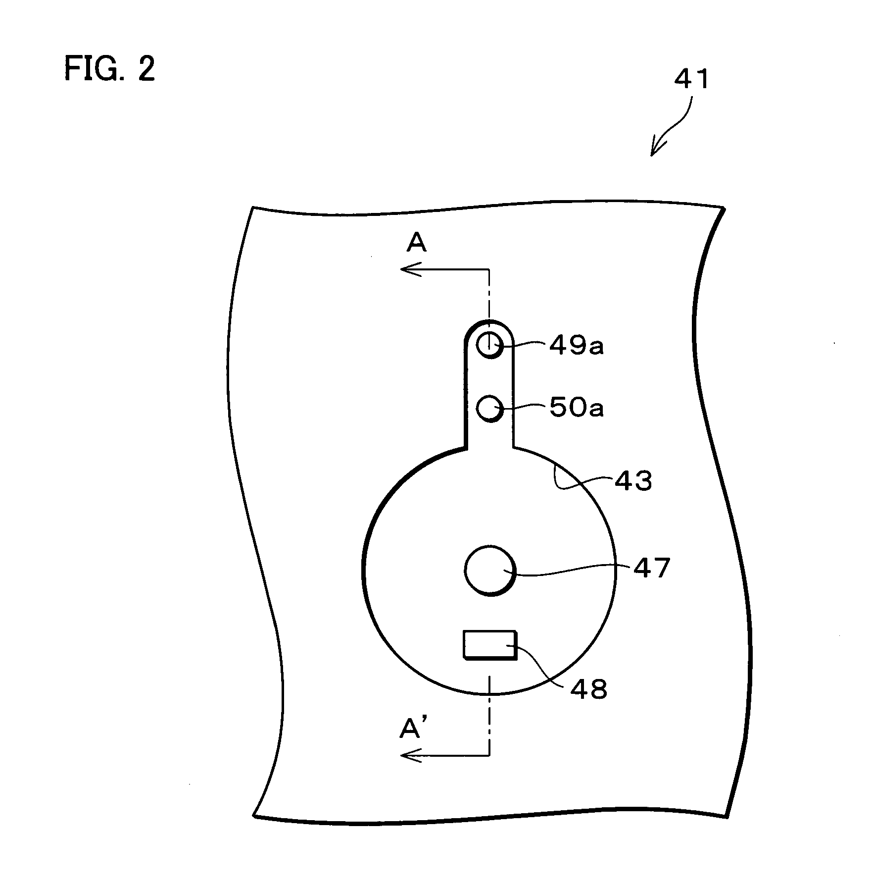
[0029]FIG. 2 is a front view of a connector 41 in a DC regulated power supply of another embodiment of the present invention, and FIG. 3 is a cross-sectional view taken on line A-A′ of FIG. 2 and a cross-sectional view of the corresponding part of a power supply cable 42.

[0030] Note that, in the present embodiment, in the DC regulated power supply used as the AC adapter described before, the power supply cable 42 is interchangeable. With this arrangement, the AC adapter has a jack 43 attached thereto, and the power supply cable 42 has a plug 44 attached to its end. The jack 43 is the one for interchangeably connecting a plurality of plugs 44 of the power supply cables 42 mutually different in impedance. The plug 44 of the power supply cable 42 has a shape varying depending on the type of the power supply lines 30. More specifically, the plu...


PUM


Abstract

In a DC regulated power supply realized as AC adapter or the like by a switching power supply, a reference voltage correction circuit, which estimates a voltage drop corresponding to a load current, corrects to increase an output voltage by changing a feedback reference value for regulation of the output voltage from a reference voltage source, in accordance with the load current sensed by the load current sensing circuit. Therefore, there occurs no negative effects that would be caused when output sensing wires are routed to a remote load. In addition, unlike the arrangement in which a reference-use rectifying circuit as well as a load-use rectifying circuit are provided, the arrangement of the switching power supply is not complicated. That is, in correcting a voltage drop, which occurs in power supply lines, corresponding to the load current, it is possible to easily perform a stable output voltage control unaffected by wire routing.

Description

[0001] This Nonprovisional application claims priority under 35 U.S.C. § 119(a) on Patent Application No. 2003 / 199748 filed in Japan on Jul. 22, 2003, the entire contents of device are hereby incorporated by reference. FIELD OF THE INVENTION [0002] The present invention relates to a DC regulated power supply suitably used as an AC (alternating-current) adapter that supplies a DC supply voltage to a load-side device via power supply lines. BACKGROUND OF THE INVENTION [0003]FIG. 4 is a block diagram of an electrical arrangement of a typical and conventional DC regulated power supply 1 used as the AC adapter. In the DC regulated power supply 1 that is a so-called switching power supply, an AC input voltage from a utility commercial power source 2 is first transformed to a DC voltage by a rectifier diode 3 and a smoothing capacitor 4. The AC input voltage from the utility power source 2 becomes the DC voltage of the smoothing capacitor 4. That is, both ends of the smoothing capacitor 4 ...

Claims


Application Information

Patent Timeline
IPC IPC(8): H02M3/28H02M3/335
CPCH02M2001/0025H02M3/33507H02M1/0025
Inventor IWASHITA, YASUHIRO
Owner SHARP KK
Why Eureka
Try Eureka