Integrated portable ultrasound imaging system

a portable ultrasound and imaging system technology, applied in the field of integrated portable ultrasound imaging systems, can solve the problems of increasing the number of time delay operations, complex physical structures required to connect each sensor to its corresponding delay, and the complexity of the beamforming processor

Inactive Publication Date: 2005-01-27
TERATECH CORP
View PDF49 Cites 31 Cited by
  • Summary
  • Abstract
  • Description
  • Claims
  • Application Information

AI Technical Summary

Benefits of technology

The invention provides a substantial advantage over prior art beamformers. For example, a device capable of steering up to one hundred beams for a ten by ten sonar array can be implemented on a single integrated circuit chip operating at a relatively low clock rate of 3.5 MegaHertz (MHZ), representing a continuous equivalent throughput rate of approximately 14 billion multiply-accumulate operations per second.

Problems solved by technology

The imparted time delays are chosen such that the signals arriving from a desired angular direction add coherently, whereas those signals arriving from other directions do not add coherently, and so they tend to cancel.
However, a beamforming processor becomes much more complex when a two dimensional sensor array is used.
Not only does the number of time delay operations increase as the square of the size of the array, but also the physical structures required to connect each sensor to its corresponding delay becomes complex.
The problem can become prohibitively complicated when the simultaneous formation of multiple beams is required.
However, the number of beams that can be implemented easily with such techniques is limited since each beam requires many discrete delay lines, or delay lines with many taps and many different weighting networks.
However, with this approach only one beam is available at a given time.
Beam control thus requires fairly complex data processors and / or signal processors to compute and supply proper commands; this is especially the case if more than one beam is to be formed simultaneously.

Method used


Image

  • Integrated portable ultrasound imaging system
  • Integrated portable ultrasound imaging system
  • Integrated portable ultrasound imaging system

Examples


Embodiment Construction

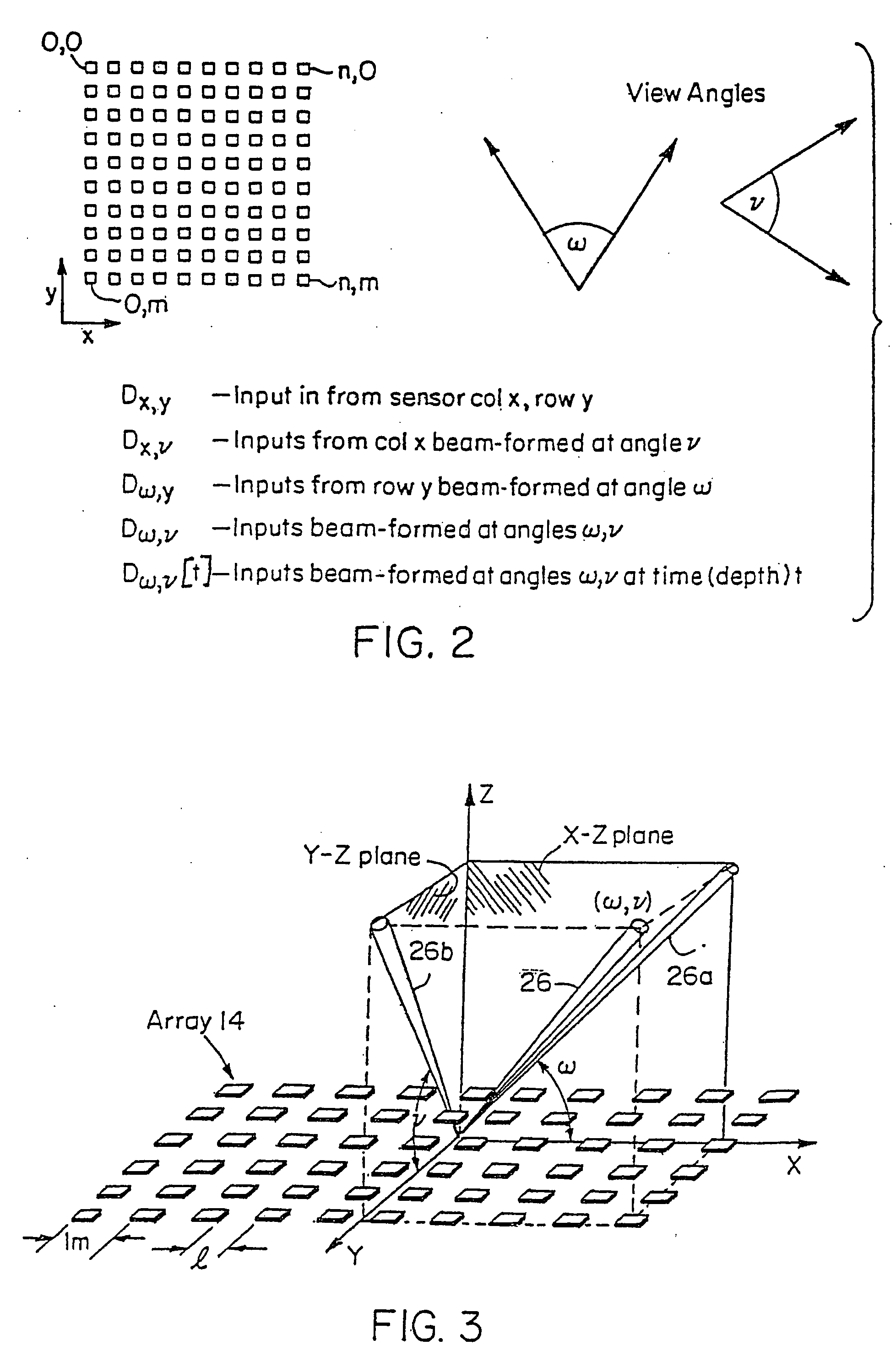
Turning attention now to the drawings, FIG. 1 illustrates a system 10 for use with a two-dimensional, planar sensor array according to the serial implementation of the invention. The system 10 shown in FIG. 1 is a beamforming system, that is, system 10 operates with sensors 12 that detect received signals. However, as will be understood from the following description, the invention also applies to beamsteering systems where the sensors 12 are transmitting signals, and the signal directions are reversed.

The beamforming system 10 consists of a number of sensors 12 arranged in a planar array 14, a number, n, of multiplexers, 17-0, 17-1 . . . 17-(n−1), a first one-dimensional (1D) beamformer 18, a transposer 20, and a second 1D beamformer 22.

The array 14 consists of a number of sensors 12 arranged in an array of m rows 15-0, 15-1, 15-(m−1), each row having n sensors 12, and n columns 16-0, 16-1, 16-(n−1) having m sensors 12. The array may or may not be square, that is, n may or may...


PUM


Abstract

A multi-dimensional beamforming device that performs consecutive one-dimensional operations. For example, beamsteering for a two-dimensional array can be include a projection of a beam onto each of the respective axes of the array. In such a device, a first beamforming processing element is used to form multiple beams for each array output along a given row. In a preferred embodiment, sequential output vectors from the first processing element are then applied to a transposing or corner turning memory and the data are reformatted such that all elements on a given column of the array are applied to a second beam forming processing element.

Description

BACKGROUND OF THE INVENTION One use of sensor arrays is to isolate signal components that are traveling from, or propagating to, a particular direction. They find use in a number of different applications. For example, sonar systems make use of sensor arrays to process underwater acoustic signals to determine the location of a noise source; arrays are also used in radar systems to produce precisely shaped radar beams. Array processing techniques for isolating received signals are known as beamforming and when the same or analogous principles are applied to focus the transmission of signals, the techniques are referred to as beamsteering. Considering the process of beamforming in particular, it is typically necessary to use a fairly large number of signal processing components to form the desired directional beams. The signal from each sensor is typically divided into representative components by subjecting each signal to multiple phase shift, or time delay, operations which cancel...

Claims


Application Information

Patent Timeline
Patent Type & Authority Applications(United States)
IPC IPC(8): G01S7/523G10K11/34H01Q3/26H01Q25/00H01Q25/04
CPCG01S7/52085G01S7/52095G01S15/8927H01Q25/00H01Q3/26H01Q3/2682G10K11/346
Inventor GILBERT, JEFFREY M.CHIANG, ALICE M.BROADSTONE, STEVEN R.
Owner TERATECH CORP
Why Eureka
Try Eureka