
Communications device used in CDMA

a communication device and mobile communication technology, applied in the direction of orthogonal multiplex, multiplex communication, wireless communication, etc., can solve the problems of limited number of channels (channel capacity) that can simultaneously make a communication, inability to adapt to modulation of control data, interference between signals of respective channels, etc., to achieve efficient transmission

Active Publication Date: 2005-01-27
FUJITSU LTD
View PDF11 Cites 30 Cited by
  • Summary
  • Abstract
  • Description
  • Claims
  • Application Information

AI Technical Summary

Benefits of technology

An object of the present invention is to implement a speedup in the data rate, and suppression of transmission power in a CDMA communications system in a well-balanced manner.
With the above described configuration, a plurality of spread codes are allocated to one user if an extra allocatable spread code exists, whereby user data can be efficiently transmitted by using code multiplexing. Namely, communications resources (spread codes here) can be effectively used.
With this configuration, user data is efficiently transmitted by using code multiplexing if an extra allocatable spread code exists, or user data is transmitted with an optimum modulation method in a communication using one spread code if an extra spread code does not exist.

Problems solved by technology

However, if a plurality of communications are simultaneously made, signals of respective channels interfere with one another.
As a result, the number of channels (a channel capacity) that can simultaneously make a communication is restricted.
Basically, the control data is not adaptively modulated.
With existing techniques, however, these requirements cannot be simultaneously satisfied.
As described above, if attempts are made to speed up a data rate with existing adaptive modulation techniques, this increases transmission power or power consumption.
Or, if attempts are made to secure constant quality under predetermined transmission power, a data rate cannot be sped up in some cases.

Method used


Image

  • Communications device used in CDMA
  • Communications device used in CDMA
  • Communications device used in CDMA

Examples


sixth embodiments

Other embodiments (second to sixth embodiments) according to the present invention are described next.

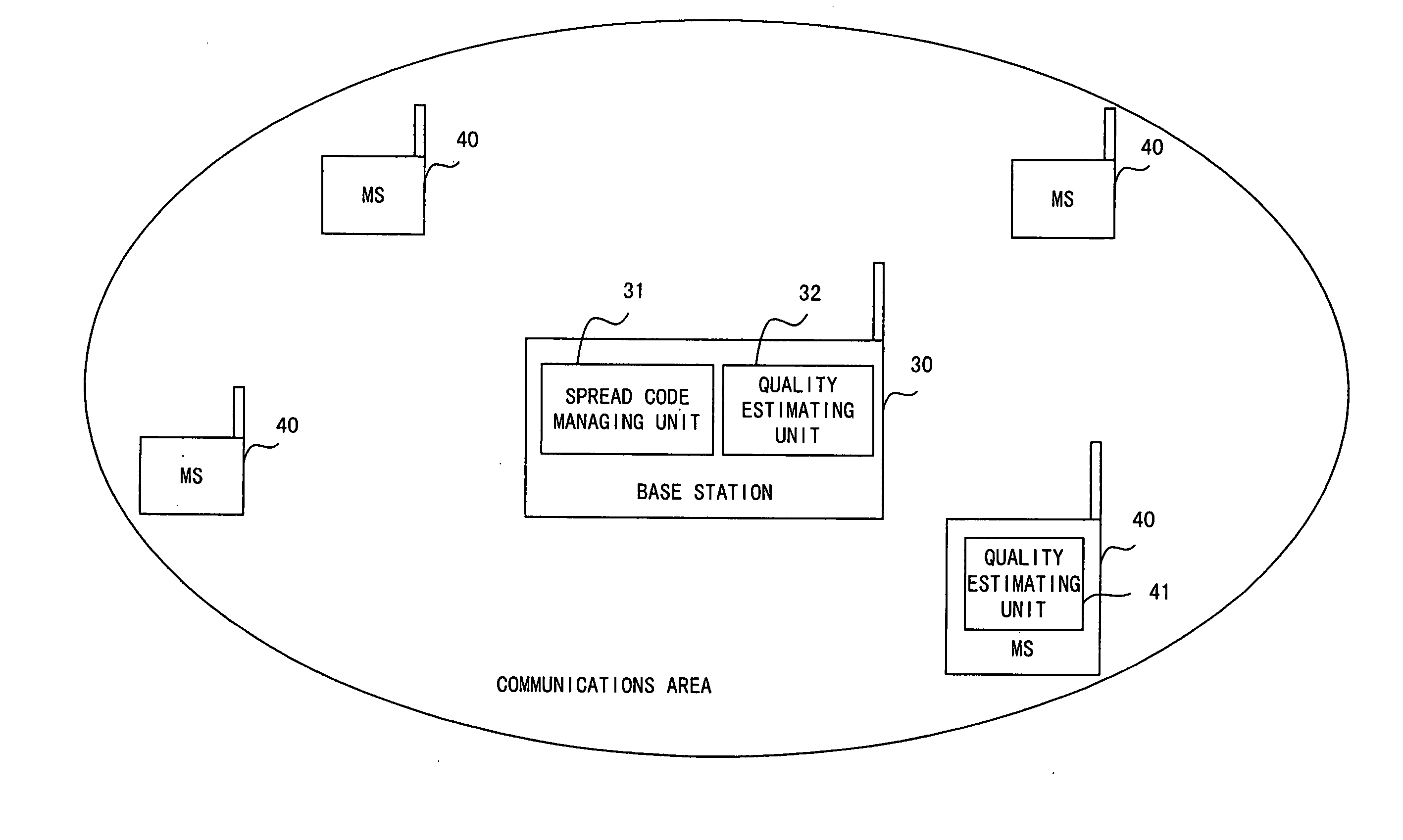
FIG. 13 is a schematic diagram showing the configuration of a base station according to a second embodiment of the present invention. In the base station according to the second embodiment, the quality of a channel between a mobile station 40 and the base station is detected or estimated in the base station. Namely, a receiving unit (DEM) 200 of the base station comprises a channel quality estimating unit 203 detecting or estimating the quality of a channel between the mobile station 40 and the base station. Here, the channel quality estimating unit 203 receives a signal transmitted from a corresponding mobile station 40, and detects or estimates a signal-to-interference ratio (SIR), an error rate, reception power, etc. A method detecting or estimating the signal-to-interference ratio (SIR), the error rate, the reception power, etc. is a known technique.

Operations of a transmittin...


PUM


Abstract

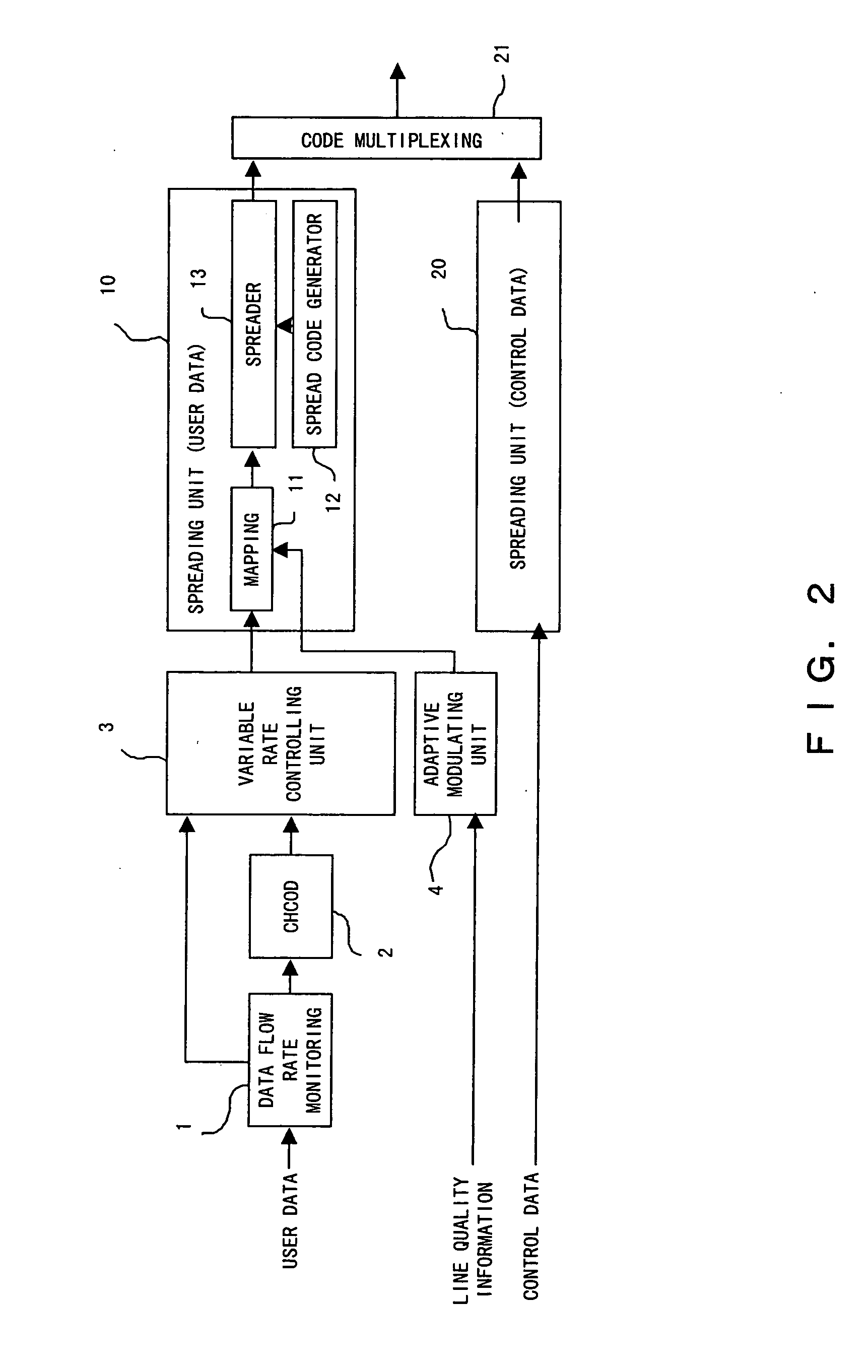
A transmitting device of the present invention is used in a CDMA communications system, and comprises: a plurality of spreading units for spreading user data; a managing unit for managing spread codes; a determining unit for determining a number of codes to be multiplexed based on use statuses of the spread codes managed by said managing unit; and a multiplexing unit for multiplexing the user data spread by spreading units a number of which corresponds to the number of codes to be multiplexed.

Description

BACKGROUND OF THE INVENTION 1. Field of the Invention The present invention relates to a communications device used in a mobile communications system using CDMA, and more particularly, to a base station device used in a mobile communications system using CDMA. 2. Description of the Related Art In recent years, development of a digital cellular wireless communications system using CDMA (Code Division Multiple Access) technology, especially, DS-CDMA (Direct Spread-CDMA) technology has been pushed forward as a next-generation mobile communications system implementing a wireless multimedia communication. In a CDMA communications system, codes are allocated to respective channels or users, and the respective channels or users are identified with the allocated codes in normal cases. Accordingly, a plurality of communications are simultaneously implemented by using the same frequency in a CDMA communications system. However, if a plurality of communications are simultaneously made, s...

Claims


Application Information

Patent Timeline
Patent Type & Authority Applications(United States)
IPC IPC(8): H04B1/707H04B7/26H04J11/00H04J13/00H04J13/10H04J13/16H04L1/00H04L27/00H04W72/04H04W76/02H04W88/02
CPCH04B1/707H04B1/7075H04B2001/70706H04B2201/70703H04L1/0022H04J13/10H04J13/16H04J13/18H04L1/0003H04J13/0077
Inventor NAKAMURA, TADASHI
Owner FUJITSU LTD
Learn More