Optical ferrule

a technology of optical ferrules and ferrules, applied in the field of connecting devices, can solve the problems of reducing alignment tolerance and more conventional packaging

Active Publication Date: 2005-01-27
REFLEX PHOTONIQUE REFLEX PHOTONICS
View PDF8 Cites 40 Cited by
  • Summary
  • Abstract
  • Description
  • Claims
  • Application Information

AI Technical Summary

Benefits of technology

[0025] 3) Because the alignment pins are recessed with respect to the flat abutment surface and the external dowel pins are not initially inserted i

Problems solved by technology

This method allows more conventional packaging and reduces the alignment tolerance becau

Method used


Image

  • Optical ferrule
  • Optical ferrule
  • Optical ferrule

Examples


Embodiment Construction

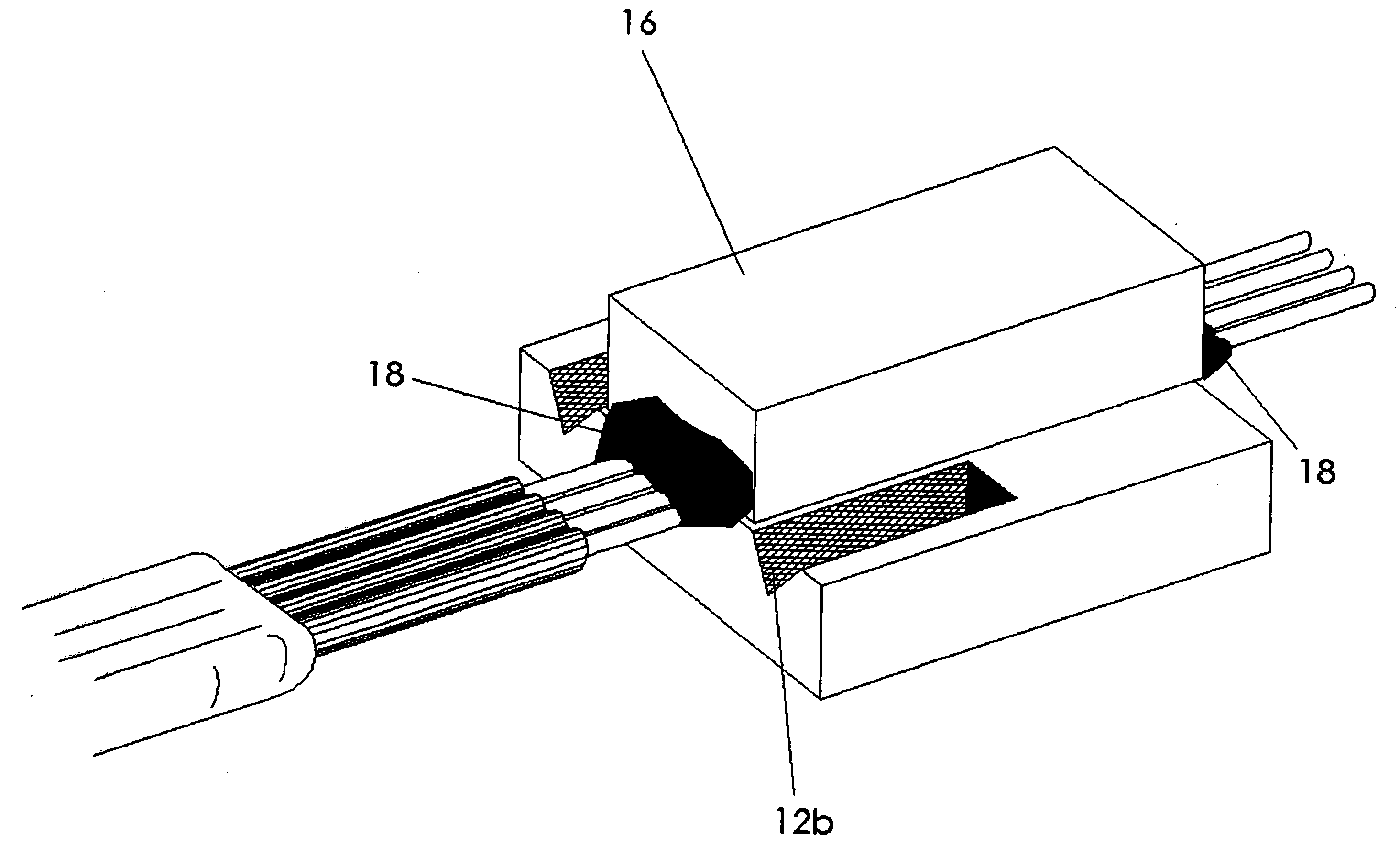
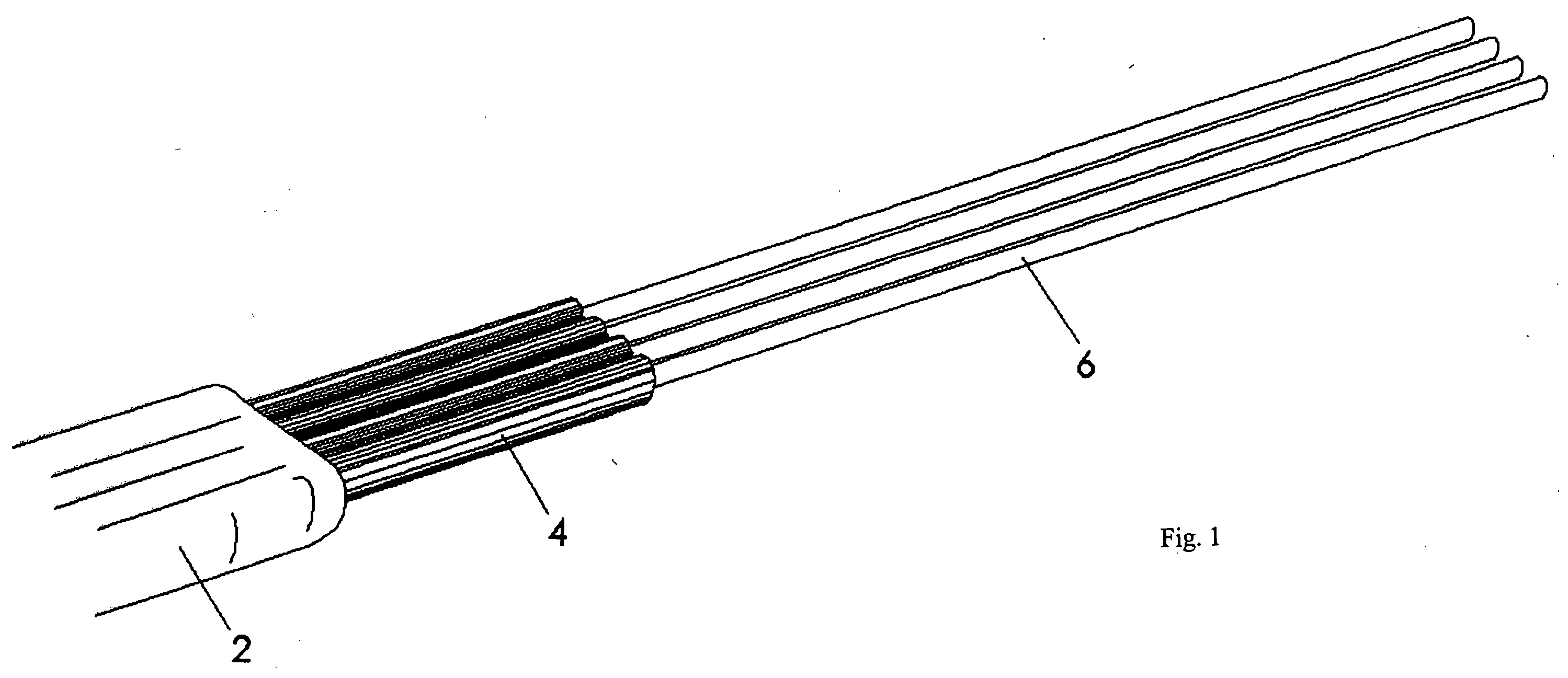
[0053] The parallel optical ferrule is a mechanical structure used to interface between a parallel optical fiber ribbon cable and an array of optoelectronic devices, such as a vertical cavity surface emitting laser (VCSEL) array or photodetector array.

[0054] The ferrule has two ends; one end interfaces with the optoelectronic device and the other end interfaces with a standard connector assembly such as the MPO / MTP™ parallel optical connector. Within the ferrule is a linear array of optical fibers that optically connects both ends of the ferrule.

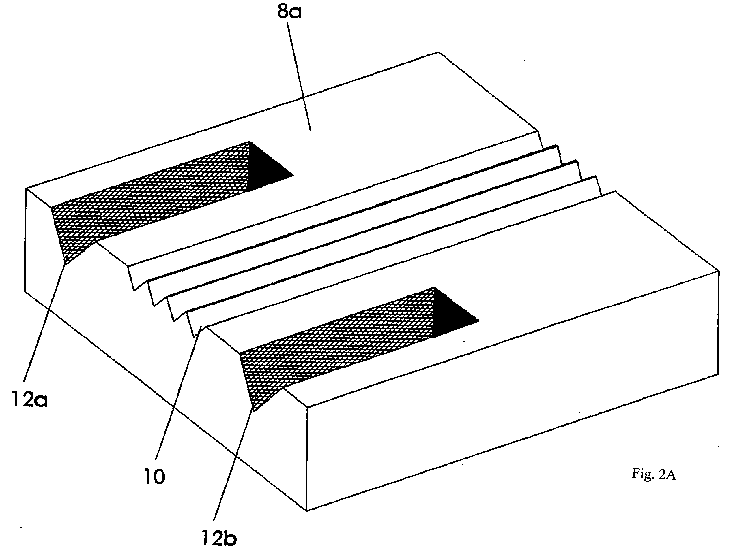
[0055] The first end of the ferrule is polished at a 45-degree angle to create a reflective glass-air interface at the fiber tips. This interface can reflect light at 90-degrees by either total internal reflection (TIR) when the glass-air interface is preserved, or by depositing a reflective metal layer on the exposed tips of the fiber. The reflective metal layer may be made of gold, silver, etc. The use of a reflective layer allows for th...


PUM


Abstract

A method and apparatus is disclosed for creating an optical ferrule. A mechanical coupling of the ferrule is achieved, at a first end of the ferrule, using at least two dowels while an optical coupling of the ferrule with an optical device is achieved, at a second end of the ferrule, using a total internal reflection.

Description

CROSS-REFERENCE TO RELATED APPLICATIONS [0001] This is the first application filed for the present invention. This application is related to commonly assigned co-pending applications filed herewith bearing agent docket numbers 16005-1US entitled “Optical Connector Assembly”, and 16005-3US entitled “Encapsulated Optical Package”, the specifications of which are hereby incorporated by reference.TECHNICAL FIELD [0002] This invention pertains to the field of connecting devices. More precisely, this invention relates to the field of optical ferrules. BACKGROUND OF THE INVENTION [0003] This invention relates to the optical coupling of light emitted, absorbed or altered by optoelectronic devices, such as photodetectors, light emitting diodes, lasers, vertical cavity surface emitting lasers (VCSEL), etc., with optical waveguides, such as optical fibers, planar waveguides, etc., which can be further coupled to standard optical connector types such as the MPO / MTP™ connector. [0004] An optoele...

Claims


Application Information

Patent Timeline
IPC IPC(8): G02B6/38G02B6/42
CPCG02B6/3839G02B6/3885G02B6/4249G02B6/4214G02B6/421
Inventor ROLSTON, DAVID ROBERT CAMERONMAJ, TOMASZ
Owner REFLEX PHOTONIQUE REFLEX PHOTONICS
Why Eureka
Try Eureka