Virtual well plate system

a virtual well and well plate technology, applied in the field of virtual well plate system, can solve the problems of not directly applicable to kinetic read assays, adds to the burden of preparation, storage and assembly of lids and bases, and uses expensive and complicated robotics

Inactive Publication Date: 2005-01-27
SCHERING CORP
View PDF11 Cites 25 Cited by
  • Summary
  • Abstract
  • Description
  • Claims
  • Application Information

AI Technical Summary

Benefits of technology

[0022] It is a further object of the present invention to provide a virtual well plate system in which even one microliter additions, which would be difficult with disposable pipette tips, are very reliable with the two plate virtual well plate system of the present invention.
[0023] In accordance with an aspect of the present invention, a virtual well plate system includes a base including a base plate having an upper surface with a hydrophobic region which defines a plurality of hydrophilic domains on the upper surface of the base plate, each hydrophilic domain adapted to hold a droplet of liquid therein; a movable lid including a lid plate having a lower surface with a hydrophobic region which defines a plurality of hydrophilic domains on the lower surface of the lid plate, each hydrophilic domain of the lid plate adapted to hold a droplet of liquid therein in a hanging manner; and a resistance arrangement mounted to at least one of the base and the lid which maintains the base and lid in an assembled condition such that the base plate and lid plate are maintained at a sufficient distance to prevent formation of virtual wells by the droplets thereon, and which permits movement of the lid toward the base upon application of an external force sufficient to overcome a resistance of the resistance arrangement in order to form the virtual wells by a combination of the droplets on the base plate and the lid plate.

Problems solved by technology

However, a problem with such known virtual well system is in regard to the assembly of the lid on the base to form the virtual wells.
In such case, it is necessary to either manually combine the lid and base or to use expensive and complicated robotics.
Therefore, since the glass plates must generally be kept separate and apart from each other, this further adds to the burden of preparation, storage and assembly of the lid and base.
Further, existing virtual well plates are not directly applicable to kinetic read assays such as the Fluorometric Imaging Plate Reader system sold under the trademark AFLIPR@ by Molecular Devices Corporation, 1311 Orleans Avenue, Sunnyvale, Calif.

Method used


Image

  • Virtual well plate system
  • Virtual well plate system
  • Virtual well plate system

Examples


first embodiment

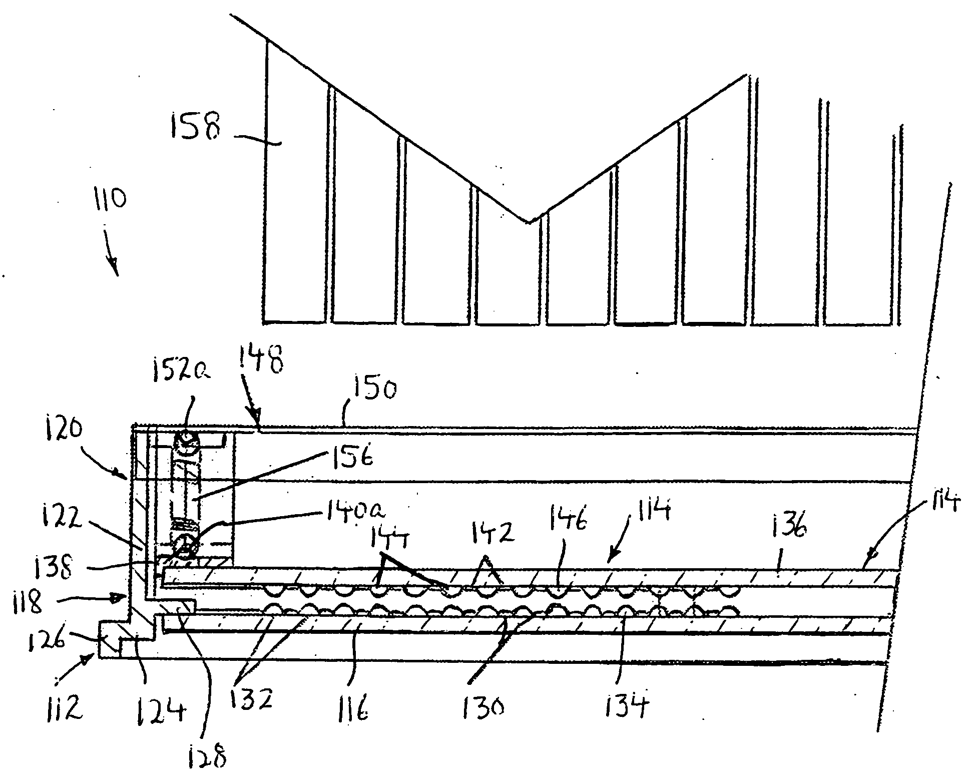
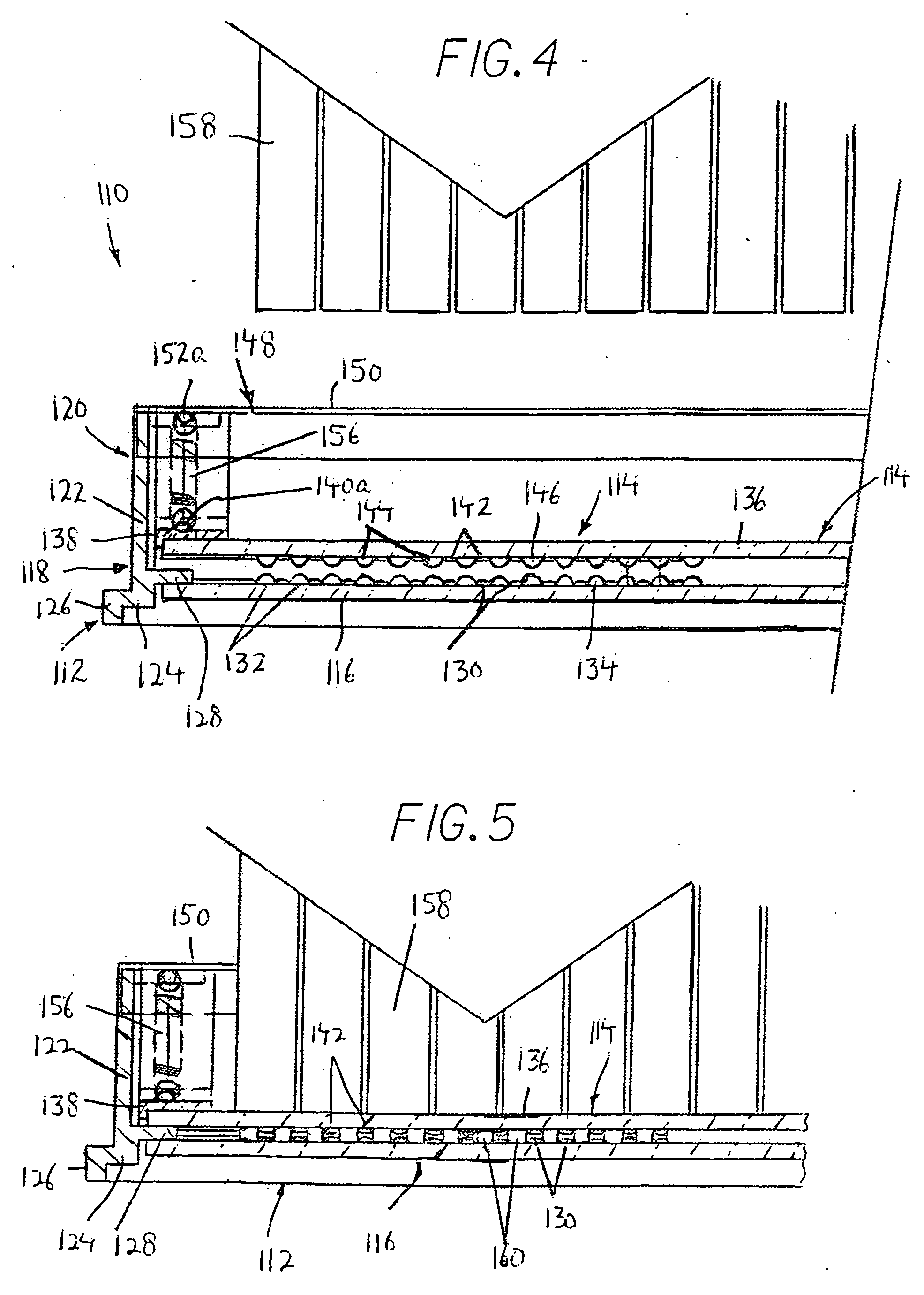
[0086] Referring now to FIG. 4, a virtual well plate system 110 according to the present invention that solves the problems associated with virtual well plate system 10, will now be discussed.

[0087] As with virtual well plate system 10, virtual well plate system 110 includes a base 112 having a glass plate 116 provided in a frame 118 made of any suitable material, including but not limited to a metal such aluminum or steel, a plastic, a thermoplastic elastomer, etc. Although glass plate 116 and frame 118 are shown to have a generally rectangular configuration, the present invention is not limited thereby. Each side wall 120 of frame 118, as shown in cross-section, includes a long vertical wall section 122 which terminates at its lower end at a short outwardly directly horizontal wall section 124, and which in turn, terminates at its outer end at a short downwardly directed vertical foot wall section 126 that supports base 112 on a surface. Further, short horizontally oriented flange...

second embodiment

[0100] For example, a virtual well plate system 210 according to the present invention is shown in FIG. 15 which will now be described, in which elements common to those of virtual well plate system 110 are identified by the same reference numerals, but augmented by 100, and therefore, a detailed explanation of these common elements will not be described. With virtual well plate system 210, base 212 is constructed in the same manner as base 110 of FIG. 14, with lower glass plate 216 sandwiched between flanges 228 and 229. However, in place of coil springs 156, at least one deformable spacer 262 is provided between lid 214 and flanges 228. Deformable structures 262 space glass plate 236 of lid 214 from glass plate 216 of base 212 by a distance of, for example, 1.85 mm, which is sufficient to prevent the touching of the different droplets and thereby to prevent the formation of the virtual wells, in the absence of a downward external force. Further, deformable spacers 262 can be secur...

third embodiment

[0104] Deformable spacers 262 can be reversible (resilient) or irreversible (non-resilient) in accordance with the present invention. FIG. 18 shows a reversible or resilient, deformable spacer 262 in the form of a cantilevered leaf spring 266 having an upwardly bowed shape. Cantilevered leaf spring 266 is preferably formed integrally as a single piece mold with base 212, and supports glass plate 236 of lid 214 in spaced relation above glass plate 216 of base 212 to prevent formation of the virtual wells. When lid 214 is pressed down, frame 238 of lid 214 presses down on cantilevered leaf spring 266 and forces cantilevered leaf spring 266 into a recess 264 of one flange 228, as shown by the dashed line in FIG. 18. When the force on lid 214 is removed, cantilevered leaf spring 266 pushes lid 214 upwardly in the original spaced apart relation with base 212. Of course, it will be appreciated that a plurality of such cantilevered leaf springs 266 are preferably provided in a plurality of...


PUM

PropertyMeasurementUnit
volumesaaaaaaaaaa
distanceaaaaaaaaaa
distanceaaaaaaaaaa

Abstract

A virtual well plate system includes a base including a base plate having an upper surface with a hydrophobic region which defines hydrophilic domains, each hydrophilic domain adapted to hold a droplet of liquid therein; a movable lid including a lid plate having a lower surface with a hydrophobic region which defines hydrophilic domains, each hydrophilic domain adapted to hold a liquid droplet in a hanging manner; and a resistance arrangement mounted to the base and/or lid and which maintains the base and lid in an assembled condition such that the base plate and lid plate are maintained at a sufficient distance to prevent formation of virtual wells by the droplets, and which permits movement of the lid toward the base upon application of an external force sufficient to overcome a resistance of the resistance arrangement, to form virtual wells by combining the droplets.

Description

[0001] This application claims the benefit of U.S. provisional patent application No. 60 / 478,801, filed Jun. 16, 2003, which is herein incorporated by reference in its entirety.BACKGROUND OF THE INVENTION [0002] The present invention relates generally to a virtual well plate system that orders and retains fluid drops in a defined spatial array, and more particularly, to a virtual well plate system that permits accurate and controlled joining of the plates to create the desired virtual wells. [0003] Because of the large volumes of data, compounds and targets, screening laboratories are required to work faster than ever in order to develop new products for market. Therefore, it is necessary to use a high-throughput screening system that delivers accurate data at a fast rate. [0004] In order to better aid in such processes, a virtual well plate system was developed, which is the subject matter of published International Application No. WO 99 / 39829 (PCT / US99 / 02300) entitled VIRTUAL WELL...

Claims


Application Information

Patent Timeline
Patent Type & Authority Applications(United States)
IPC IPC(8): B01F13/00B01L3/00C40B60/14
CPCB01F5/0085C40B60/14B01F13/0071B01F13/0084B01J2219/00317B01J2219/00328B01J2219/00364B01J2219/00387B01J2219/00585B01J2219/00596B01J2219/00659B01J2219/00691B01L3/5025B01L3/5085B01L3/50853B01L3/5088B01L2300/047B01L2300/0829B01F13/0059B01F25/14B01F33/3021B01F33/30351B01F33/30
Inventor PECHTER, DAVID S.VARGA, EDWARD G.
Owner SCHERING CORP
Why Eureka
Try Eureka