Method and apparatus for preventing cross-contamination of multi-well test plates

a multi-well test plate and cross-contamination technology, applied in the field of multi-well test plate and tube array, can solve the problems of significant cross-contamination risk of samples, inconvenient sealing of the tops of wells, and inability to reliably use tapes

a multi-well test plate and cross-contamination technology, applied in the field of multi-well test plate and tube array, can solve the problems of significant cross-contamination risk of samples, inconvenient sealing of the tops of wells, and inability to reliably use tapes

US20050019225A1Inactive Publication Date: 2005-01-27SANADI ASHOK RAMESH

Image

  • Method and apparatus for preventing cross-contamination of multi-well test plates
  • Method and apparatus for preventing cross-contamination of multi-well test plates
  • Method and apparatus for preventing cross-contamination of multi-well test plates

Examples


Embodiment Construction

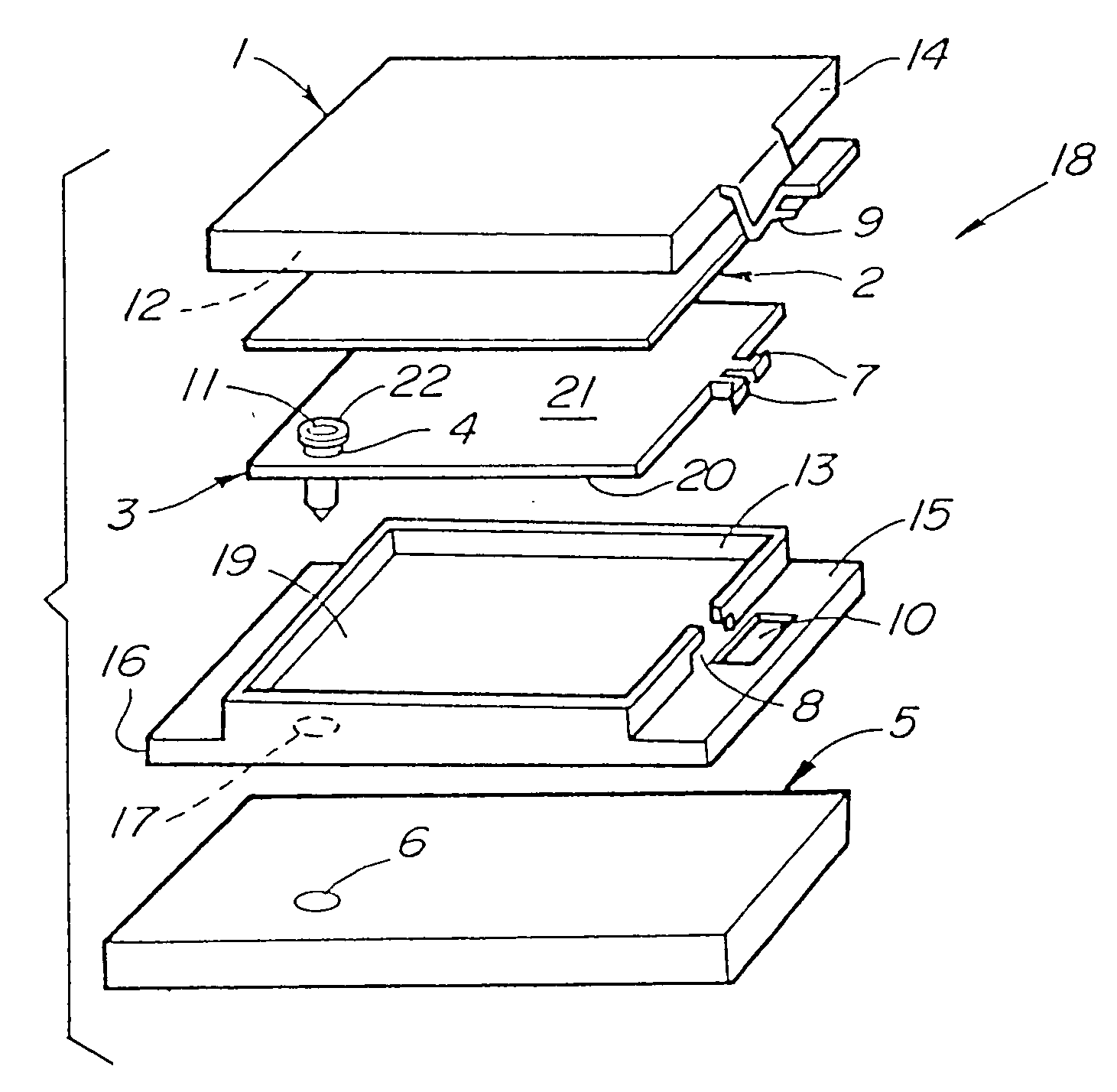
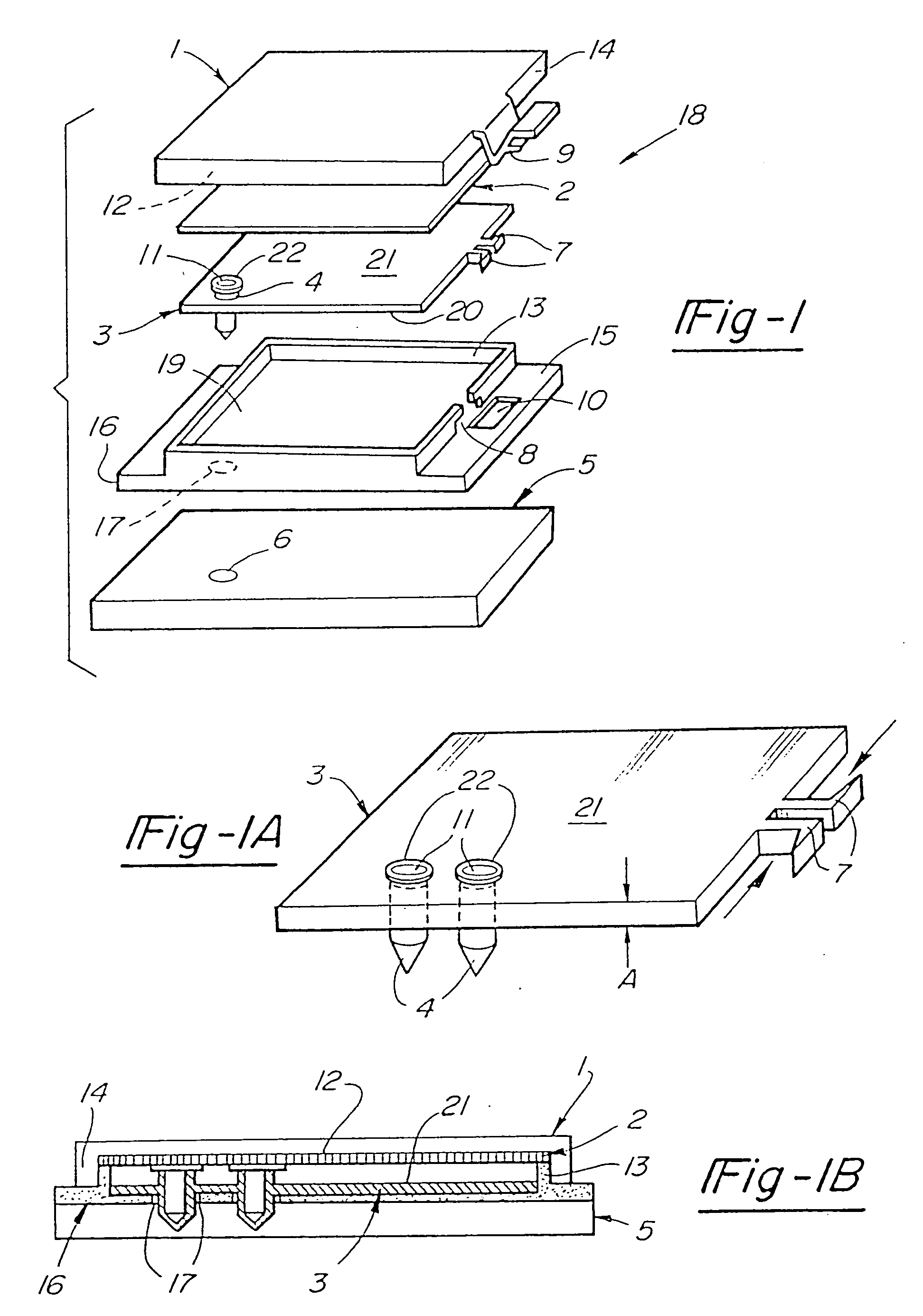
[0045] Referring to FIG. 1 of the drawings, in one embodiment assembly 18 is shown with tube tray 3 having a plurality of tubes 4, only one of which is shown in FIG. 1 for the sake of clarity. Each tube 4 is provided with an opening or mouth 11. It will be appreciated that tray 3 may be formed as an integral or single-piece structure having tubes 4 or that tubes 4 may be formed as discrete units which are subsequently attached to tube tray 3 either temporarily or permanently. For example, tube tray 3 could comprise a plate with plurality of openings in which tubes 4 are held in the nature of a test-tube rack, with a holding or retaining plate being fixed reversibly and temporarily to the plate thereby holding the tubes in place. Tube tray 3 is preferably placed in tray carrier 16 having a principal surface 19 which mates with lower surface 20 of tube tray 3. Portions of tubes 4 which extend below lower surface 20 are received through holes 17 of tray carrier 16 into bores 6 of base ...


PUM


Abstract

A multi-well plate which prevents cross-contamination of samples through the use of a resilient gasket which covers a majority of the top of the plate and is compressed by a lid having a clamp assembly. It thus provides a sealing assembly for arrays of containers of any size or shape. The gaskets may be unitary sheets with or without an array of openings corresponding to the well openings or may consist of discrete single well gaskets. A multi-tube array is also provided which can be sealed without the need of a gasket or tight-fitting caps. A multi-well plate is also disclosed in which samples can be gas-equilibrated without the risk of microbial contamination.

Description

[0001] This application is a continuation-in-part of application Ser. No. 08 / 049,171, filed Apr. 19, 1993 entitled “Method and Apparatus For Preventing Cross-Contamination of Multi-Well Test Plates” the entire disclosure of which is incorporated herein by reference.TECHNICAL FIELD OF THE INVENTION [0002] This invention relates generally to multi-well plates and tube arrays in which Samples (biological, chemical, etc.) are analyzed or processed. More specifically, the present invention solves the problem associated with cross-contamination of samples which may occur in the use of a closely spaced array of wells or tubes. The present invention also relates to a multi-well plate which can be used for analysis or processing in a controlled atmosphere without the possibility of contamination from atmospheric sources. In addition, the present invention describes a new type of multi-well plate which can be clamped together. BACKGROUND OF THE INVENTION [0003] A number of laboratory and clin...

Claims


Application Information

Patent Timeline
27 Jan 2005
Publication
US20050019225A1
IPC
B01L3/00
CPC
B01L3/5025; B01L3/50255; Y10T436/25375; B01L3/50853; Y10T436/255; B01L3/5085
Inventors
SANADI, ASHOK RAMESH