
Low temperature fuel cell power plant operation

a fuel cell and power plant technology, applied in the field of low temperature fuel cell power plant operation, can solve the problems of low fuel cell performance, cell dry out, reduced service life of fuel cell power plant, etc., and achieve the effect of inherent resistan

Active Publication Date: 2005-01-27
AUDI AG
View PDF12 Cites 12 Cited by
  • Summary
  • Abstract
  • Description
  • Claims
  • Application Information

AI Technical Summary

Benefits of technology

[0015] Some example systems designed according to this invention have a heater associated with the enthalpy recovery device. The heater may be operated by a controller, the inputs of which may be the fuel cell power plant operating conditions, such as temperature, or environmental conditions, such as ambient temperature and pressure. In one example, the heater comprises a resistive element that heats up responsive to current supplied to the element.

Problems solved by technology

If the PEM were to dry out, the cell resistance increases, which lowers the fuel cell performance.
Additionally, if the membrane dries out, it degrades, which results in reduced service life for the fuel cell power plant.
If the exhaust temperature exceeds 110° F., there is a water deficiency and the cells will dry out.
If the exhaust temperature is less than 110° F., a system water surplus results, possibly flooding the cells unless the water is removed as liquid.
A particular challenge is presented when the ambient temperatures are low such that water or liquid associated with or processed by the ERDs may freeze.
Under such conditions, the enthalpy recovery device may not function as required and the power plant system water balance may not be maintained, which could result in performance degradation or a reduced service life of the system.

Method used


Image

  • Low temperature fuel cell power plant operation
  • Low temperature fuel cell power plant operation
  • Low temperature fuel cell power plant operation

Examples


Embodiment Construction

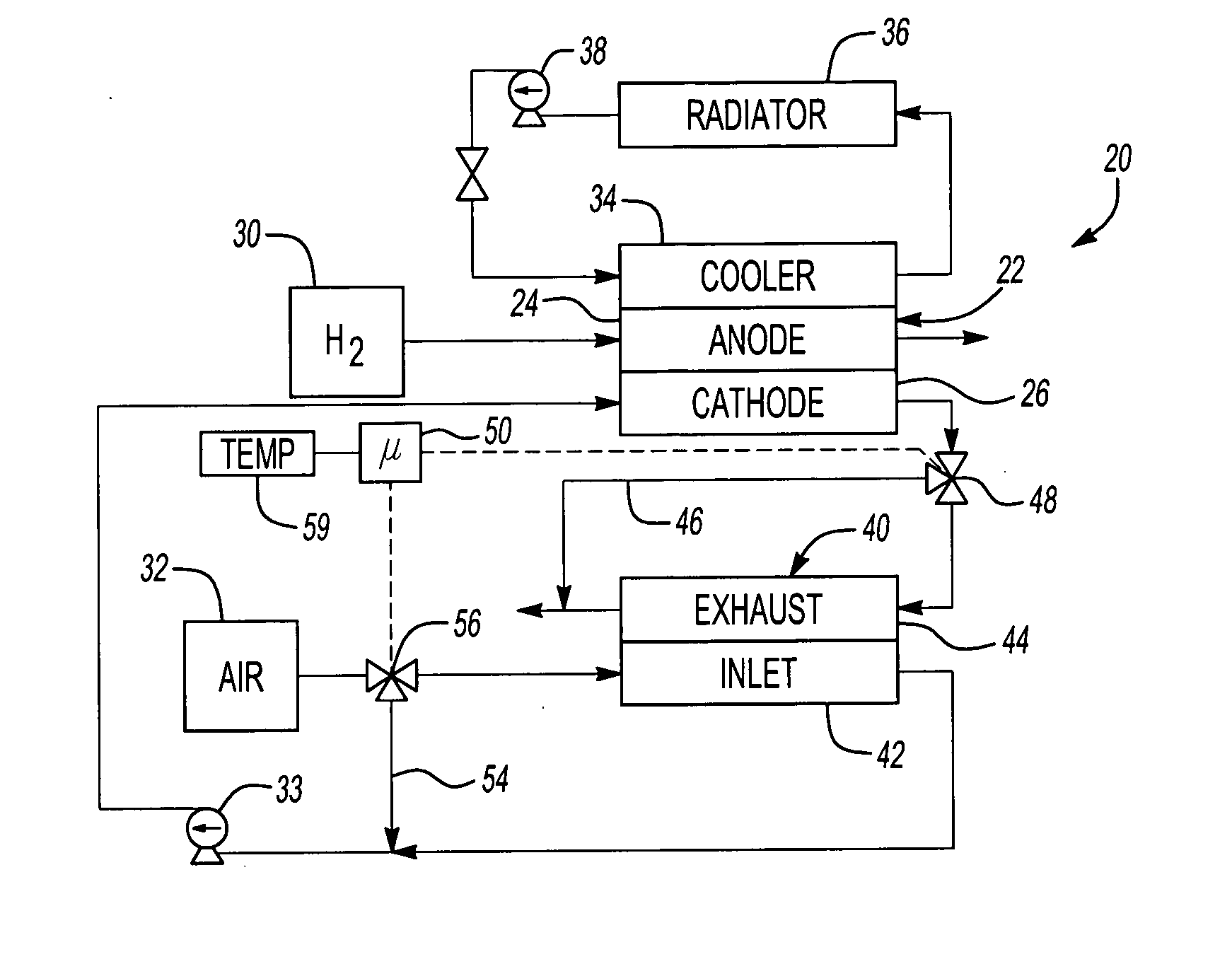
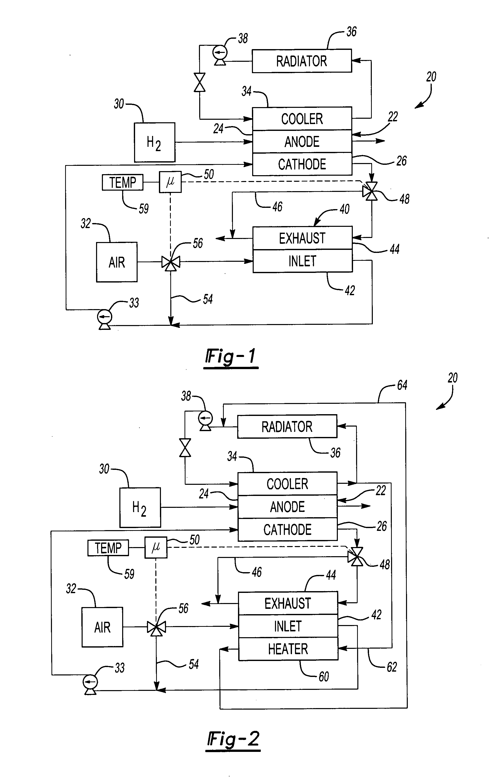
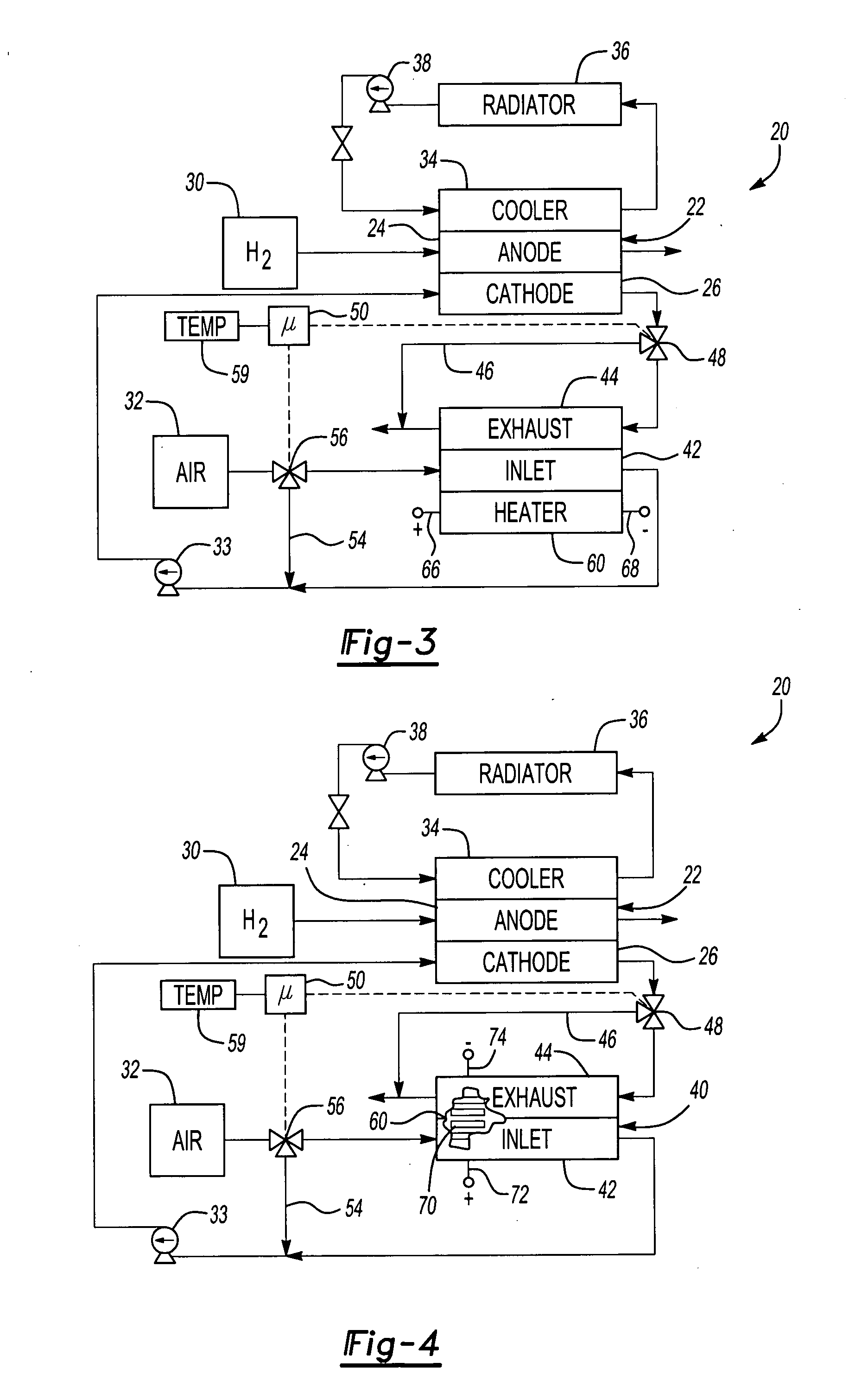
[0023]FIG. 1 schematically illustrates a fuel cell power plant system 20. A fuel cell 22 includes a first electrode 24 and a second electrode 26. The example fuel cell 22 is a proton exchange membrane fuel cell stack, the operation of which is known. The first electrode 24 in this example is the fuel cell anode and receives fuel, such as hydrogen or a hydrogen-containing gas, from a fuel source 30. The second electrode 26 in this example is the cathode and receives an oxidant, such as air, from a source 32, which is provided to the cathode 26 through action of a pump 33. The anode and cathode may be a single fuel cell plate, or a plurality of plates, as known.

[0024] The illustrated example includes a coolant loop associated with the fuel cell 22. Coolant loops are known and take a variety of forms. Coolant flowing through a cooler portion 34 passes through a radiator 36, such as a conventional heat exchanger. A pump 38 maintains the desired flow through the coolant loop.

[0025] An ...


PUM


Abstract

A fuel cell power plant system includes the ability to operate an enthalpy recovery device even under cold conditions. A bypass arrangement allows for selectively bypassing one or more portions of the enthalpy recovery device under selected conditions. In one example, the enthalpy recovery device is completely bypassed under selected temperature conditions to allow the device to freeze and then later to be used under more favorable temperature conditions. In another example, the enthalpy recovery device is selectively bypassed during a system startup operation. One example includes a heater associated with the enthalpy recovery device. Another example includes preheating oxidant supplied to one portion of the enthalpy recovery device.

Description

BACKGROUND OF THE INVENTION [0001] This invention generally relates to operating a fuel cell power plant during cold temperature conditions. More particularly, this invention relates to selectively utilizing an enthalpy recovery device based upon operating conditions of a fuel cell power plant. [0002] Fuel cell power plants are well known and used to produce electrical power from reducing and oxidizing fluids. Fuel cell structures and fuel cell power plant arrangements are known and come in a variety of configurations. Many fuel cells utilize a proton exchange membrane (PEM) as part of a chemical process for producing electrical energy. [0003] In proton exchange membrane fuel cells, it is important that the reactants are humidified to prevent the PEM from drying out. If the PEM were to dry out, the cell resistance increases, which lowers the fuel cell performance. Additionally, if the membrane dries out, it degrades, which results in reduced service life for the fuel cell power plan...

Claims


Application Information

Patent Timeline
IPC IPC(8): H01M8/04H01M8/06
CPCH01M8/04014H01M8/04022H01M8/04029H01M8/04037H01M8/04119Y02T90/32H01M8/04223H01M8/0606H01M2250/20Y02E60/50H01M8/04141H01M8/04225H01M8/04302Y02T90/40
Inventor CLARK, THOMAS M.MARGIOTT, PAUL R.GRASSO, ALBERT P.BREAULT, RICHARD D.VAN DINE, LESLIE L.STEINBUGLER, MARGARET M.BLUDNICKI, EDWARD J.
Owner AUDI AG
Learn More