Method for manufacturing electrode for fuel cell

a fuel cell and manufacturing method technology, applied in the direction of cell components, final product manufacturing, sustainable manufacturing/processing, etc., can solve problems such as defective intimacy, and achieve the effects of preventing the shifting of the surface layer part of the electrode, reducing spray pressure, and reducing the amount of was

Inactive Publication Date: 2005-01-27
HONDA MOTOR CO LTD
View PDF18 Cites 40 Cited by
  • Summary
  • Abstract
  • Description
  • Claims
  • Application Information

AI Technical Summary

Benefits of technology

In this way, in this forming method, by a spraying device being disposed above the electrode and a resin solution being sprayed through this spraying device to apply the resin solution to the electrode, a shear force can be prevented from arising at the electrode. Also, by spraying a resin solution including a gas, it is possible to keep the spray pressure down. By this means, when the resin solution is applied to the electrode, the surface of the electrode is prevented from shifting.
Additionally, by a resin solution including a gas being sprayed, when the resin solution is sprayed at the edge of the electrode, the atomization pressure arising at the edge of the electrode, that is, the shear force, can be kept small. By this means, the shear force arising at the electrode can be kept small, and a surface layer part of the electrode shifting can be prevented.
Also, by the electrode being surrounded with an outer side regulating wall member, when the resin solution is applied to the electrode surface, the resin solution can be formed along the outer side regulating wall member. As a result, the edge of the ion exchange film can be formed well.

Problems solved by technology

The present inventors discovered that the cause of areas of defective intimacy arising between the layers is that when a next solution is applied after a previously applied film has hardened, this solution does not permeate the previously applied film, and defective intimacy arises as a result.
Similarly, they discovered that also when a solution is applied to an ion exchange film in the form of a sheet, the solution does not permeate the sheet-form ion exchange film, and defective intimacy arising as a result constitutes another cause.

Method used


Image

  • Method for manufacturing electrode for fuel cell
  • Method for manufacturing electrode for fuel cell
  • Method for manufacturing electrode for fuel cell

Examples


seventh embodiment

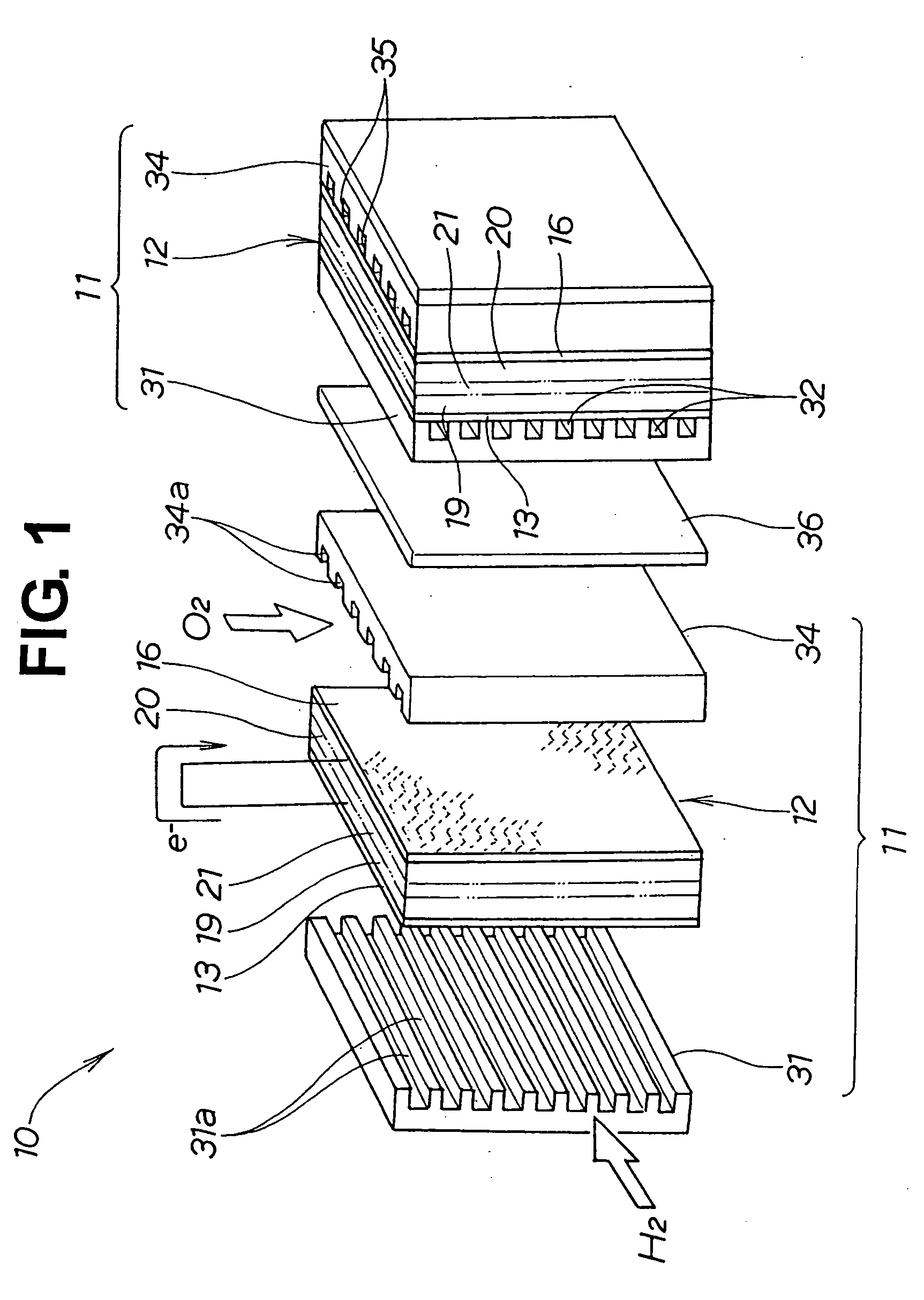
FIG. 18 shows a fuel cell shown in exploded perspective view having a fuel cell electrode pertaining to the invention.

A fuel cell unit 400 is made up of a plurality of (in the example shown in the figure, two) fuel cells 411, 411. Each fuel cell 411 is made by providing an ion exchange film for a fuel cell (simply called an ion exchange film) 414 on a negative pole (electrode) 412, superposing a positive pole (electrode) 416 on this ion exchange film 414, disposing a negative electrode side flow channel plate 421 on the outer side of the negative electrode 412, and disposing a positive electrode side flow channel plate 424 on the outer side of the positive electrode 416. A plurality (two) of these fuel cells 411 are provided with a separator 426 between them to constitute the fuel cell unit 400.

By the negative electrode side flow channel plate 421 being stacked against the negative electrode 412, flow channels 421a in the negative electrode side flow channel plate 421 are covered...

eighth embodiment

FIG. 30 is an exploded perspective view of a fuel cell having a fuel cell electrode according to the invention.

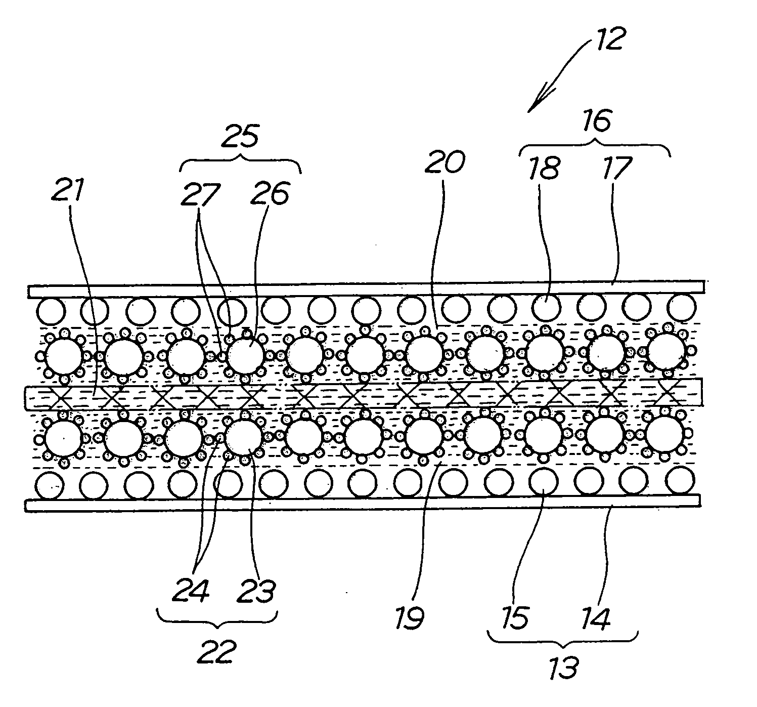
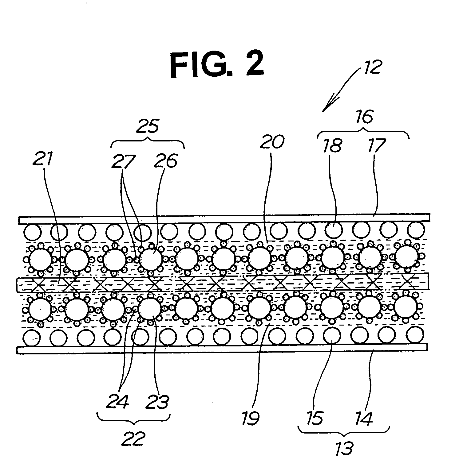
A fuel cell unit 600 of this embodiment is made up of a plurality of (in this example, two) fuel cells 611, 611. Each fuel cell 611 has a negative electrode plate 612, an ion exchange film 615, a positive electrode plate 616 stacked against the ion exchange film 615, a negative electrode side flow channel plate 621 disposed on the outer side of the negative electrode plate 612, and a positive electrode side flow channel plate 624 disposed on the outer side of the positive electrode plate 616. The negative electrode 612 is made up of a negative substrate 613 and a negative pole (electrode) 614. The positive electrode plate 616 is made up of a positive substrate 617 and a positive pole (electrode) 618.

A plurality of these fuel cells 611 are provided with separators 626 between them to constitute the fuel cell unit 600.

By the negative electrode side flow channel plate 621...


PUM

PropertyMeasurementUnit
porosityaaaaaaaaaa
porosityaaaaaaaaaa
melting pointaaaaaaaaaa

Abstract

A fuel cell electrode is proposed which has a positive electrode layer (20), a negative electrode layer (19) and an ion exchange film (21) interposed between these. Before a solution for making one of the other of positive and negative electrodes has dried, a solution for making the ion exchange film is applied to it, and then a solution for making the other electrode is applied while the solution for making the ion exchange film is not yet dry. Because the layers are not dry, the intimacy of the layers improves. By the ion exchange film being made a solution, the applied film can be made thin.

Description

TECHNICAL FIELD This invention relates to a method for manufacturing an electrode for use in a fuel cell which has an ion exchange film disposed between positive and negative electrodes and generates electricity by hydrogen being brought into contact with a catalyst in the negative electrode and oxygen being brought into contact with a catalyst in the positive electrode. BACKGROUND ART FIG. 33 and FIG. 34 hereof show a fuel cell electrode of related art. In this fuel cell electrode 700, an ion exchange film 703 is disposed between a negative electrode layer (hydrogen electrode) 701 and a positive electrode layer (oxygen electrode) 702, and an electrical current is generated by a hydrogen molecules (H2) being brought into contact with a catalyst included in the negative electrode layer 701 and oxygen molecules (02) being brought into contact with a catalyst included in the positive electrode layer 702 to cause electrons e− to flow as shown by the arrow. In the generation of the curr...

Claims


Application Information

Patent Timeline
Patent Type & Authority Applications(United States)
IPC IPC(8): H01M4/86H01M4/88H01M4/92H01M4/96H01M8/10
CPCH01M4/8605H01M4/861H01M4/8657Y02E60/521H01M4/921H01M8/1004H01M2008/1095H01M4/886Y02P70/50Y02E60/50H01M4/88
Inventor KAKUTANI, OSAMUOKIYAMA, GENSUZUKI, TAKASHISHIBATA, TETSUOKAMIYAMA, YOUICHIWATANABE, HIDEKIDATE, TOMOKOHIRANO, YOSHIKI
Owner HONDA MOTOR CO LTD
Why Eureka
Try Eureka