Optical coherence tomography system for the examination of human or animal tissue or of organs

a coherence tomography and optical coherence technology, applied in the field of optical coherence tomography system for the examination of human or animal tissue or organs, can solve the problems of large amount of data, need to use additional movement mechanisms, and the doctor generally has no possibility of manually guiding the catheter

Active Publication Date: 2005-01-27
SIEMENS HEALTHCARE GMBH
View PDF6 Cites 90 Cited by
  • Summary
  • Abstract
  • Description
  • Claims
  • Application Information

AI Technical Summary

Benefits of technology

[0019] A further embodiment of the invention combines the three-dimensional view derived by the evaluation unit with an additional three-dimensional view obtained from a different examination modality, with both three-dimensional views having known positions in the coordinate system of the position-determining system. This embodiment of the invention combines a three-dimensional morphological data set, which may have been derived from 3D-angiography or 3D-ultrasound, with the three-dimentional view data derived from optical coherence tomography. If the positions of both data sets i

Problems solved by technology

This leads to a large amount of data, since cross-sectional views are obtained even though the catheter may not have moved at all.
A disadvantage of this procedure is the ne

Method used


Image

  • Optical coherence tomography system for the examination of human or animal tissue or of organs
  • Optical coherence tomography system for the examination of human or animal tissue or of organs
  • Optical coherence tomography system for the examination of human or animal tissue or of organs

Examples


Embodiment Construction

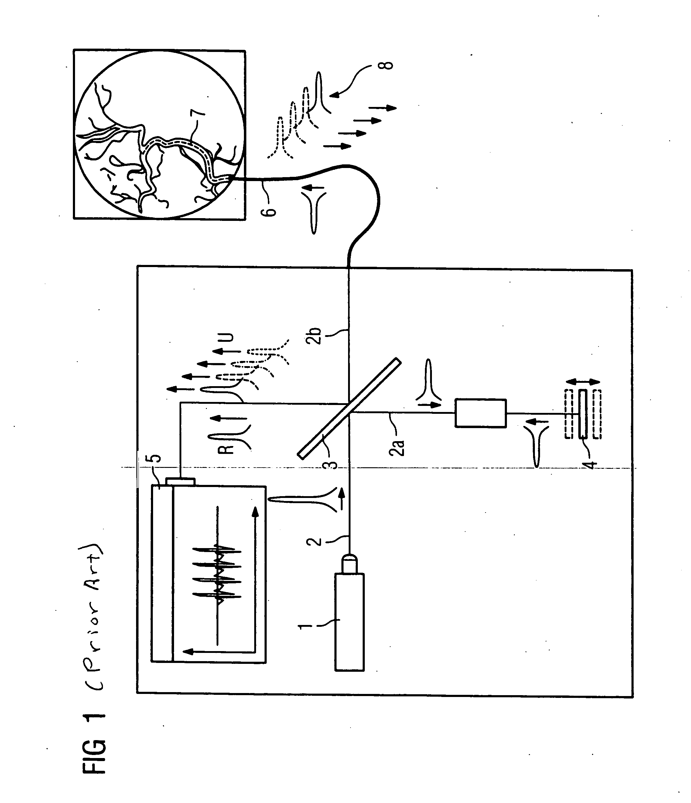
[0024]FIG. 1 explains the basic concept of optical coherence tomography. A light source, a laser 1 in the present example, emits a ray of light 2 toward a semi-transparent mirror 3. A first part 2a of the light ray is deflected to a reference branch, where the length of ray 2a is modulated by means of a movable mirror 4, for example. The modulated reflected light strikes the semi-transparent mirror 3 and continues as reference light component R toward an interferometer 5.

[0025] A second part 2b of the light ray enters a catheter 6, which is inserted into a vessel 7 in this example. The light is emitted from the tip of catheter 6 and shines on the tissue of the vessel 7. The reflected light, which is also modulated depending on the position of the reflecting surface as indicated by the four reflection light symbols 8, again enters the catheter 6, continues to the semi-transparent mirror 3 and from there continues as a reflected examination light component U to the interferometer 5. ...


PUM


Abstract

An optical coherence tomography system for the examination of human or animal tissue or of organs includes a catheter insertable into the tissue or organ, by which light is introduced into the tissue or organ and the reflection is transmitted to an evaluation unit, where the reflection and a reference light are evaluated interferometrically to determine a two-dimensional cross-sectional view of the tissue or organ under examination. The evaluation unit uses several two-dimensional cross-sectional views to derive a three-dimensional view of the tissue or organ under examination. At least one position sensor is contained on or in the tip of the catheter, and a position-determining system derives position data, which describe the current position of the position sensor in the coordinate system of the position-determining system. The position-determining system also captures position data regarding the spatial position of the cross-sectional views in the coordinate system of the position-determining system, and the evaluation system derives the three-dimensional view from the cross-sectional views and the corresponding position data.

Description

BACKGROUND OF THE INVENTION [0001] 1. Field of the Invention [0002] The present invention proposes an optical coherence tomography system for the examination of human or animal tissue or organs of the type including a catheter that is insertable into the tissue or organ, by which light is introduced into the tissue or organ and the reflection is transmitted to an evaluation unit, where the reflection and a reference light are evaluated interferometrically to generate a two-dimensional cross-sectional view of the tissue or organ, wherein the evaluation unit uses several two-dimensional cross-sectional views to derive a three-dimensional view of the tissue or organ, and wherein at least one position sensor is disposed on or in the tip of the catheter, as part of a position-determining system for deriving position data describing the current position of the position sensor in the coordinate system of the position-determining system. [0003] 2. Description of the Prior Art [0004] Optical...

Claims


Application Information

Patent Timeline
IPC IPC(8): A61B5/00G06T17/40
CPCA61B5/0066A61B5/0084G06T19/00A61B5/6852A61B5/065
Inventor KLEEN, MARTINRAHN, NORBERT
Owner SIEMENS HEALTHCARE GMBH
Why Eureka
Try Eureka